
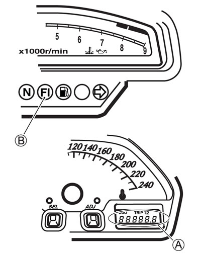
User mode
| MALFUNCTION | LCD (DISPLAY) INDICATION A | FI INDICATOR LIGHT INDICATION B | INDICATION MODE |
| "NO" | Odometer *1 | — | — |
| "YES" Engine can start | Odometer (*1) and "FI" letters *2 | FI indicator light turns ON. | Each 2 sec. Odometer (*1) and "FI" are indicated alternately. |
| Engine can not start | "FI" letter *3 | FI indicator light turns ON and blinks. | "FI" is indicated continuously. |
*1: Current letter displayed any one of the Odometer, Tripmeter or Clock.
*2: When one of the signals is not received by ECM, the fail-safe circuit works and injection is not stopped. In this case, "FI" and Odometer (*1) are indicated in the LCD panel and motorcycle can run.
* 3: The injection signal is stopped, when the crankshaft position sensor signal, tip-over sensor signal, both #1/#2 ignition signals, both #1/#2 injector signals, fuel pump relay signal or ignition switch signal is not sent to ECM. In this case, "FI" is indicated in the LCD panel. Motorcycle does not run.
"CHEC": The LCD panel indicates "CHEC" when no communication signal from the ECM is received for 3 seconds.
For Example:
- The ignition switch is turned ON, and the engine stop switch is turned OFF. In this case, the speedometer does not receive any signal from ECM, and the panel indicates "CHEC".
- If CHEC is indicated, the LCD does not indicate the trouble code. It is necessary to check the wiring harness between ECM and speedometer couplers.
- The possible cause of this indication is as follows;
- Engine stop switch is in OFF position. Side-stand/ignition inter-lock system is not working. Ignition fuse is burnt.
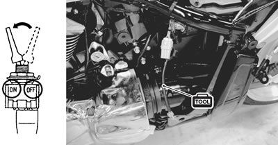
Dealer mode
The defective function is memorized in the computer. Use the special tool's coupler to connect to the dealer mode coupler. The memorized malfunction code is displayed on LCD (DISPLAY) panel. Malfunction means that the ECM does not receive signal from the devices. These affected devices are indicated in the code form.
- 09930-82720: Mode select switch
Caution: Before checking the malfunction code, do not disconnect the ECM lead wire couplers. If the couplers from the ECM are disconnected, the malfunction code memory is erased and the malfunction code can not be checked.
| MALFUNCTION | LCD (DISPLAY) INDICATION | FI INDICATOR LIGHT INDICATION | INDICATION MODE |
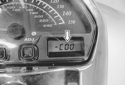
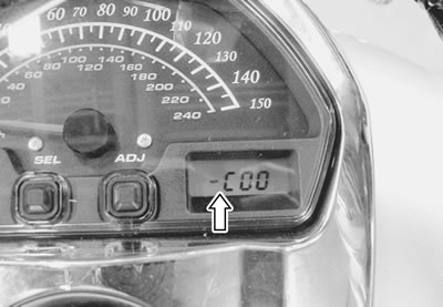
| "NO" | C00 | FI indicator light turns OFF. | — |
| "YES" | C**code is indicated from small numeral to large one. | For each 2 sec., code is indicated. |
| CODE | MALFUNCTION PART | REMARKS |
| C00 | None | No defective part |
| C12 | Crankshaft position sensor (CKPS) | Pick-up coil signal, Generator |
| C13 | Intake air pressure sensor #2 (IAPS #2) | For Front cylinder |
| C14 | Throttle position sensor (TPS) | *1 |
| C15 | Engine coolant temp. sensor (ECTS) | |
| C17 | Intake air pressure sensor #1 (IAPS #1) | For Rear cylinder |
| C21 | Intake air temp. sensor (IATS) | |
| C23 | Tip-over sensor (TOS) | |
| C24 | Ignition signal #1 (IG coil #1.1) | For Rear cylinder |
| C25 | Ignition signal #2 (IG coil #2.1) | For Front cylinder |
| C26 | Ignition signal #1 (IG coil #1.2) | For Rear cylinder |
| C27 | Ignition signal #2 (IG coil #2.2) | For Front cylinder |
| C28 | Secondary throttle valve actuator (STVA) | |
| C29 | Secondary throttle position sensor (STPS) | *2 |
| C31 | Gear position signal (GP switch) | |
| C32 | Injector signal #1 (FI #1) | For Rear cylinder |
| C33 | Injector signal #2 (FI #2) | For Front cylinder |
| C40 | Idle speed control valve (ISC valve) | |
| C41 | Fuel pump control system (FP control system) | Fuel pump, fuel pump relay |
| C42 | Ignition switch signal (IG switch signal) | Anti-theft |
| C44 | Heated oxygen sensor #2 (HO2S #2) | For E-02, 19, 24 |
| C46 | Exhaust control valve actuator (EXCVA) | |
| C49 | PAIR control solenoid valve #2 (PAIR valve #2) | Except for E-03, 28, 33 |
| C60 | Cooling fan control system | Cooling fan relay |
| C61 | PAIR control solenoid valve #1 (PAIR #1) | |
| C64 | Heated oxygen sensor #1 (HO2S #1) | For E-02, 19, 24 |
In the LCD (DISPLAY) panel, the malfunction code is indicated from small code to large code.
*1: To get the proper signal from the throttle position sensor, the sensor basic position is indicated in the LCD (DISPLAY) panel. The malfunction code is indicated in three digits. In front of the three digits, a line appears in any of the three positions, upper, middle or lower line. If the indication is upper or lower line when engine rpm is 900 r/min, slightly turn the throttle position sensor and bring the line to the middle. In the normal condition, the throttle valve stop screw pushes throttle valves slightly, and middle line will be indicated.
*2: When the secondary throttle valve actuator and secondary throttle position sensor signals are not sent to ECM. In this case, C28 and C29 are indicated alternately.
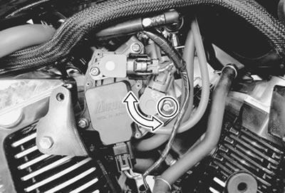
TPS adjustment
1. Warm up the engine and check the engine idle r/min.
Adjust the engine rpm to 900 r/min if necessary. (6-22)
2. Connect the special tool (Mode select switch) to the dealer mode coupler at the wiring harness.
3. Remove the fuel tank. (6-3)
4. Remove the right air cleaner box. (6-13)
5. If the throttle position sensor adjustment is necessary, loosen the screw and turn the throttle position sensor and bring the line to the middle.
6. Then, tighten the screw to fix the throttle position sensor.
- 09930-11950: Torx wrench
- 09930-82720: Mode select switch
The LCD displays the line for 0.4 sec. at a time, and when such a display repeats two times, it indicates the current position where the sensor is fixed.
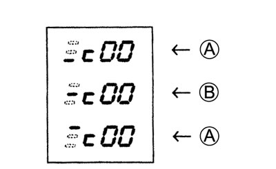
A. Incorrect; B. Correct position