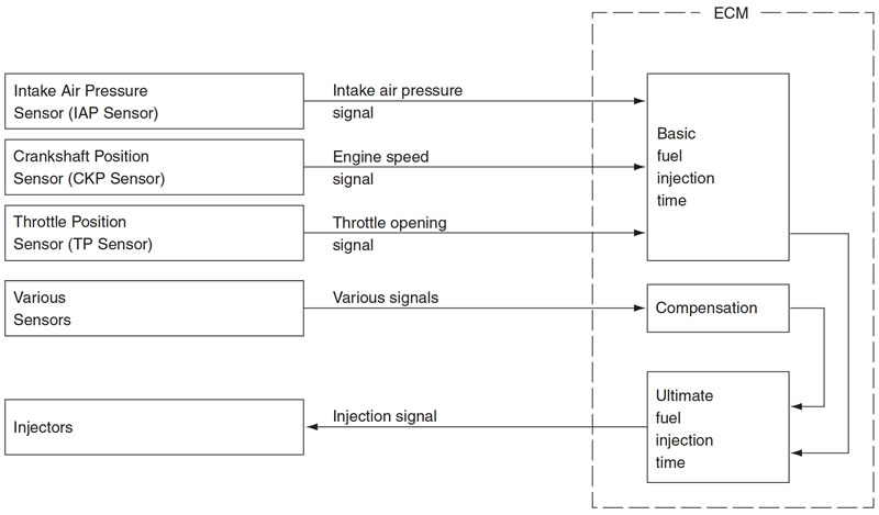
Injection time (injection volume)
The factors to determine the injection time include the basic fuel injection time, which is calculated on the basis of intake air pressure, engine speed and throttle opening angle, and various compensations.
These compensations are determined according to the signals from various sensors that detect the engine and driving conditions.
Compensation of injection time (volume)
The following different signals are output from the respective sensors for compensation of the fuel injection time (volume).
Injection stop control
| SIGNAL | DESCRIPTION |
| ENGINE COOLANT TEMPERATURE SENSOR SIGNAL | When engine coolant temperature is low, injection time (volume) is increased. |
| INTAKE AIR TEMPERATURE SENSOR SIGNAL | When intake air temperature is low, injection time (volume) is increased. |
| HEATED OXYGEN SENSOR SIGNAL (FOR E-02, 19, 24) | Air/fuel ratio is compensated to the theoretical ratio from density of oxygen in exhaust gasses. The compensation occurs in such a way that more fuel is supplied if detected air/fuel ratio is lean and less fuel is supplied if it is rich. |
| BATTERY VOLTAGE SIGNAL | ECM operates on the battery voltage and at the same time, it monitors the voltage signal for compensation of the fuel injection time (volume). A longer injection time is needed to adjust injection volume in the case of low voltage. |
| ENGINE RPM SIGNAL | At high speed, the injection time (volume) is increased. |
| STARTING SIGNAL | When starting engine, additional fuel is injected during cranking engine. |
| ACCELERATION SIGNAL/ DECELERATION SIGNAL | During acceleration, the fuel injection time (volume) is increased, in accordance with the throttle opening speed and engine rpm. During deceleration, the fuel injection time (volume) is decreased. |
Injection stop control
| SIGNAL | DESCRIPTION |
| TIP-OVER SENSOR SIGNAL (FUEL SHUT-OFF) | When the motorcycle tips over, the tip-over sensor sends a signal to the ECM. Then, this signal cuts OFF current supplied to the fuel pump, fuel injectors and ignition coils. |
| OVER-REV. LIMITER SIGNAL | The fuel injectors stop operation when engine rpm reaches rev. limit rpm. |
FI System parts location
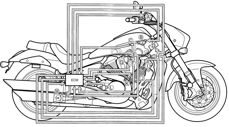
A. Tachometer; C. Intake air pressure sensor #2 (IAPS); E. Secondary throttle position sensor (STPS); G. Secondary throttle valve actuator (STVA); I. Ignition coil/plug cap #2; K. HO2 sensor #1 (HO2S) [For E-02, 19, 24]; M. Exhaust control valve actuator (EXCVA); B. ISC valve (ISCV); D. Ignition coil #1 (IG COIL); F. Throttle position sensor (TPS); H. PAIR control solenoid valve (For E-02, 19, 24); J. HO2 sensor #2 (HO2S) [For E-02, 19, 24]; L. Gear position switch
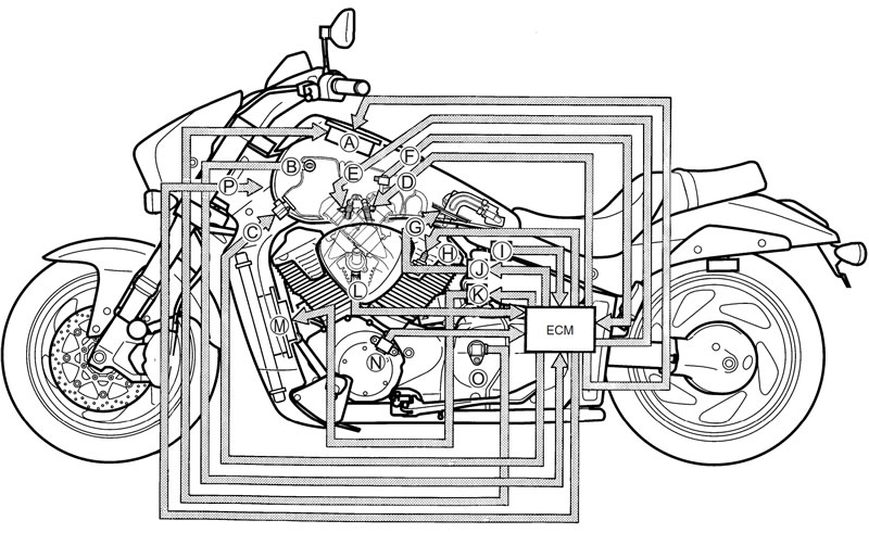
A. Speedometer; C. PAIR control solenoid valve; E. Fuel injector #2; G. Fuel pump; I. Tip-over sensor (TOS); K. Cooling fan relay; M. Cooling fan; O. Speedmeter sensor; B. Intake air temperature sensor (IATS); D. Fuel injector #1; F. Intake air pressure sensor #1 (IAPS); H. Ignition coil/plug cap #1; J. Fuel pump relay (FP RELAY); L. Engine coolant temperature sensor (ECTS); N. Crankshaft position sensor (CKPS); P. Ignition coil #2 (IG COIL)