Prepare
1. Raise rear wheel. See Motorcycle general maintenance, Secure the Motorcycle for Service.
2. Right Shock Absorber: Remove muffler. See Removing and installing muffler.
Remove
1. See Figure 3-46. Remove shock absorber.
- a. Remove lower screw (4).
- b. Remove upper screw (3), cover (2) and shock absorber (1).
Figure 3-46. Shock Absorber: 1. Shock absorber; 2. Cover; 3. Upper screw; 4. Lower screw
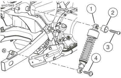
Figure 3-47. Cover
Install
| FASTENER | TORQUE VALUE | |
| Shock absorber lower screw | 61.0-68.0 Nm | 45-50 ft·lbs |
| Shock absorber upper screw | 61.0-68.0 Nm | 45-50 ft·lbs |
1. See Figure 3-46. Install shock absorber.
- a. Install shock absorber (1).
- b. Install lower screw (4). Tighten to 61.0-68.0 Nm (45-50 ft·lbs).
- c. See Figure 3-47. Install cover with triangle facing forward.
- d. See Figure 3-46. Install upper screw (3). Tighten to 61.0-68.0 Nm (45-50 ft·lbs).
Clean and inspect
1. Inspect shock absorber for signs of leakage. Replace both shock absorbers if leak is found.
2. Inspect bushings for cracks and wear. Replace as necessary.
Adjust preload
| PART NUMBER | TOOL NAME |
| HD-51439 | SHOCK ADJUSTMENT SPANNER |
Warning: Adjust both shock absorbers equally. Improper adjustment can adversely affect stability and handling, which could result in death or serious injury.
Notice: Do not turn the shock absorber adjustment collar clockwise beyond adjustment setting 5. Doing so may result in equipment damage.
Note: See Figure 3-48. Do not turn the preload cam past position five (5) to position one (1) or from position one (1) to position five (5).
1. See Figure 3-49. Adjust rear shocks.
- a. Refer to Table 3-11.
- b. Using SHOCK ADJUSTMENT SPANNER (Part No. HD-51439), turn the adjustment cam to specification.
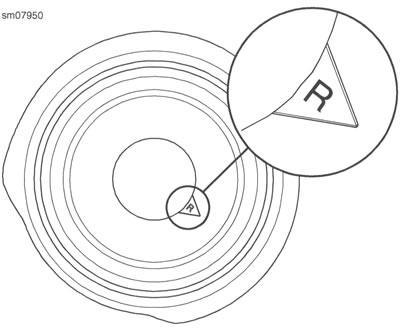
Figure 3-48. Shock Preload Cam Positions (typical)
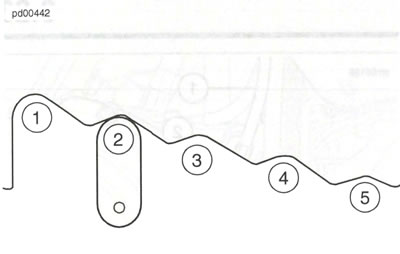
Figure 3-49. Shock Absorber Preload Adjustment
Table 3-11. Recommended Shock Preload: Five Position
| LOAD* | POSITION |
| Less than 75 kg (165 1b) | 1 |
| 75-89 kg (165-195 lb) | 2 |
| 89-102 kg (195-225 lb) | 3 |
| 102-116 kg (225-255 lb) | 4 |
| 116 kg (255 lb) to maximum added weight allowed. | 5 |
* Add the weight of the rider, passenger, riding gear, accessories, and cargo.
Table 3-12. Maximum Added Weight Allowed
| MODEL | MAX LOAD | |
| kg | lb | |
| XG500 | 182 | 402 |
| XG750 | 182 | 402 |
Complete
1. Right Shock Absorber: Install muffler. See Removing and installing muffler.
2. Lower rear wheel.
Disposal
Note: The damper reservoir contains nitrogen gas and oil under pressure. Do not drill into the oil chamber.
1. Support the shock absorber in a vise.
2. See Figure 3-50. Use a center punch to start a hole between the weld and the reservoir body.
Warning: Do not expose shock absorber to heat source. Exposure to heat source can build excessive gas pressure, which could cause explosion and result in death or serious injury.
Warning: Discharging pressurized oil and gas can pierce skin and cause flying debris, which could cause serious injury. Wear safety glasses and gloves.
Notes:
- A 6/64 through 1/8 in drill bit can be used.
- Use a sharp drill bit to prevent excessive heat buildup when discharging.
3. Drill at the punch mark, retracting the drill as it penetrates the shell.
4. Allow gas to escape.
5. Dispose of shock absorber.
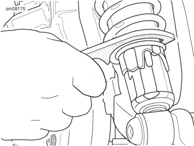
Figure 3-50. Center Punch/Drill Hole Location
