
Note: The starter clutch can be removed with the engine in the frame. If the engine has been removed, ignore the steps which do not apply.
Check
1. The operation of the starter clutch can be checked while it is in situ. Remove the starter motor (see Chapter 9). Check that the starter drive gear is able to rotate freely anticlockwise as you look at it via the starter motor aperture, but locks when rotated clockwise. If not, the starter clutch is faulty and should be removed for inspection.
Removal
2. Remove the alternator rotor - the starter clutch is mounted on the back of it (see Chapter 9). If the starter driven year does not come away with the starter clutch, slide it off the crankshaft.
Inspection
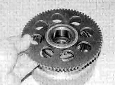
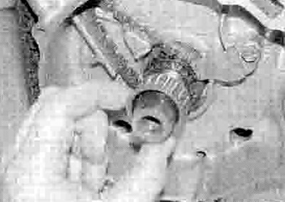
3. With the alternator rotor face down on a workbench, check that the starter driven gear rotates freely in an anti-clockwise direction and locks against the rotor in a clockwise direction (see illustration). If it doesn't, the starter clutch should be dismantled for further investigation.
22.3. Check that the starter driven gear rotates freely anti-clockwise
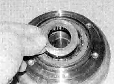
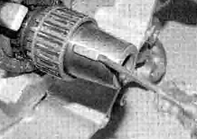
4. Withdraw the starter driven gear from the starter clutch (see illustration). If the gear appears stuck, rotate it anti-clockwise as you withdraw it to free it from the starter clutch. On XL models, remove the thrust washer (see illustration).
22.4a. Withdraw the gear...
22.4b ...and on XL models remove the thrust washer
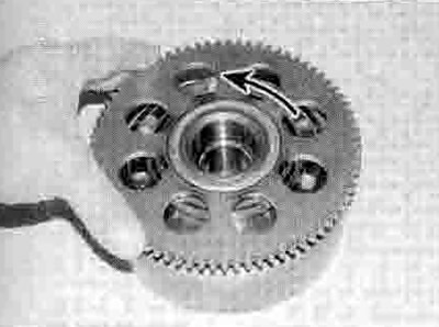
5. Check the condition of the sprags inside the clutch body and the corresponding surface on the driven gear hub (see Illustration). If they are damaged, marked or flattened at any point, they should be replaced with new ones. Measure the outside diameter of the hub and check that it has not worn beyond the service limit specified. To remove the sprag assembly, hold the rotor using a holding strap and unscrew the bolts inside the rotor (see illustration). Remove the sprag housing from the rotor and the sprag assembly from the housing, noting how it fits. Install the new assembly In a reverse sequence. Apply clean engine oil to the sprags. Apply a suitable non-permanent thread locking compound to the bolts and tighten them to the torque setting specified at the beginning of the Chapter.

22.5a. Check the condition of the sprags and gear hub as described
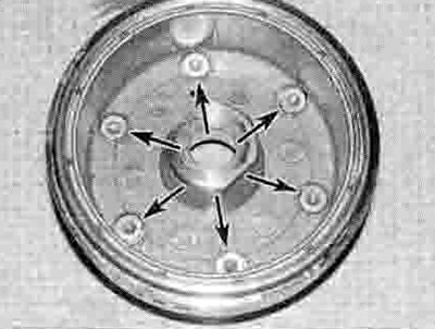
22.5b. Sprag assembly bolts (arrowed)
6. Slide the needle roller bearing off the crankshaft - you will have to remove the Woodruff key first if not already done (see illustrations). Check the bearing and its corresponding surfaces in the starter driven gear hub and on the crankshaft. If the bearing surfaces show signs of excessive wear or the bearing itself is worn or damaged, they should be replaced with new ones. Measure the inside diameter of the hub and check that it has not worn beyond the service limit specified.
22.6a. Remove the Woodruff key...
22.6b ...and slide the bearing off the shaft
7. Check the teeth of the starter motor drive shaft, starter drive gear, idle/reduction gear and starter driven gear. Replace the gears and/or starter motor if worn or chipped teeth are discovered on related gears. Also check the starter drive gear and idle/reduction gear shafts for damage, and check that the gears are not a loose fit on the shaft. Replace the shafts with new ones if necessary.
Installation
8. Lubricate the needle roller bearing with clean engine oil and slide it on the crankshaft (see illustration 22.6b). Fit the Woodruff key (see illustration 22.6a).
9. On XL models, install the thrust washer (see illustration 22.4b). Lubricate the outside of the starter driven gear hub with clean engine oil, then fit the gear into the clutch, rotating it anti-clockwise as you do so to spread the sprags and allow the hub to enter (see illustration 22.4a)
10. Install the alternator rotor (see Chapter 9).