Removed carburetor bar (see «Plank carburetors - removal and installation»).
Disassembly
Attention!
- Before starting work on disassembling and washing the carburetor, we prepare the workplace: the workbench must be absolutely clean, it is desirable that there is a minimum of dust in the air.
- We lay clean paper on the workbench - we will put all the removed parts on it.
- Carburettors should be disassembled sequentially without removing them from the bar. It is not allowed to rearrange similar parts from one carburetor to another, as some parts (jets, emulsion tubes) carburetors of external and internal cylinders differ in throughput and other parameters. In addition, rearranging parts will disrupt the running-in of mating surfaces.
1. Using pliers with narrow jaws, open the spring clamp and slide it up the tube. We repeat the procedure on the second tube.

2. Remove the fuel supply pipe.

3. Using pliers with narrow jaws, open the spring clamps, move them up and remove from the fittings two tubes for communicating the float chambers with the atmosphere.
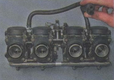
4. Remove the return spring of the drive bar for starting enrichers.
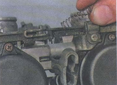
Attention! Plastic washers are installed under the fastening screws of the concentrator drive bar to ensure the bar sliding. It is important not to lose them!
5. Using a Phillips screwdriver, unscrew the two screws securing the concentrator drive bar.

6. Remove the drive bar of starting enrichers by disengaging the brackets on the bar and the concentrator rods.

7. With a 10 mm ring wrench, unscrew the concentrator housing and remove it.
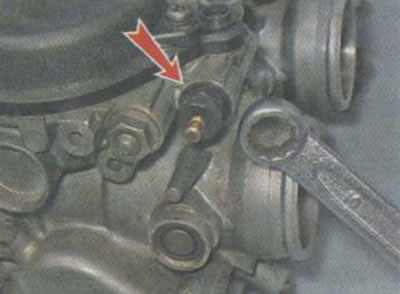
8. Remove the enricher return spring.
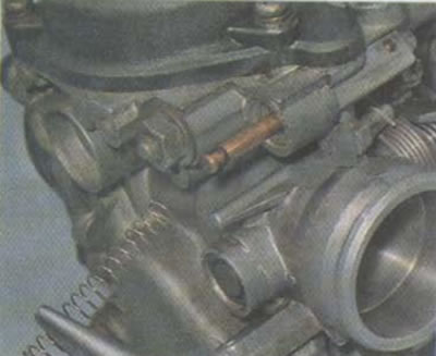
9. Remove the enrichment valve assembly with the rod.

10. Using a Phillips screwdriver, unscrew the three screws securing the cover of the vacuum membrane.
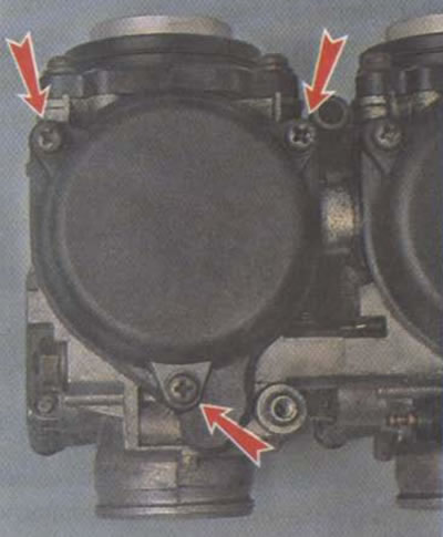
Attention! Remove the vacuum diaphragm cover carefully. The lid gasket is made as a single piece with the membrane, it can stick to the lid, it can be easily damaged when removed.
11. Remove the cover.

Attention! The throttle return spring must also be handled very carefully and must not be stretched, compressed or deformed. The spring is calibrated and any deformation will result in the carburetor not working properly.
12. Remove the throttle valve return spring.
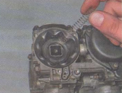
13. Carefully remove the throttle valve assembly with the vacuum membrane.

14. Inspect the membrane. If cracks, holes, tears, other mechanical damage are noticeable on it, the rubber is warped or hardened, the membrane assembly with the throttle must be replaced.
Attention!
- Do not seal the membrane or try to restore it by other means. The resistance to deformation of the membrane is strictly calibrated, and with any change in its shape (patches, a layer of glue, other materials) the membrane will not work correctly, the carburetor will also not function correctly, and will not be adjustable.
- Before you start to remove the screw «quality», it is recommended to fill the screw seat with penetrating grease or kerosene. The screw socket is directed downward, and is often clogged with dirt flying from the road, which prevents the screw from being turned out.
15. Using a thin slotted screwdriver, unscrew the screw «quality» mixtures.
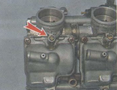
16. Remove the screw assembly with the spring, metal washer and rubber sealing ring.
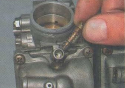
17. Inspect the screw «quality». If the needle is deformed or broken, the screw must be replaced. If the rubber sealing ring is defective, it must also be replaced. Poor quality screw needle seal «quality» will lead to a malfunction of the carburetor and the impossibility of its adjustment.

18. Using a Phillips screwdriver, unscrew the three screws securing the float chamber cover.
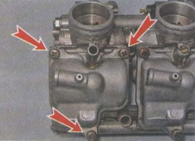
19. Remove the cover of the float chamber.
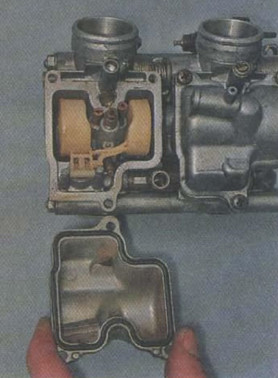
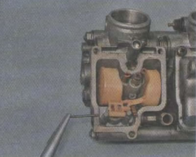
20. Use pliers with narrow jaws to remove the float axis.
21. Take out the float assembly with the locking needle.
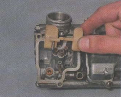
22. Separate the shut-off needle from the float and inspect it. If wear is noticeable on the working edge of the needle, mechanical damage, the needle ceases to securely lock the valve and needs to be replaced. So it’s better to replace it immediately - the needle cannot be repaired. We check the needle stop pin located on its back side. The pin should sink freely, without jamming, into the needle body and independently return to its original position under the action of a return spring. If washing does not produce results, the needle must be replaced.
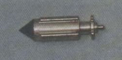
23. Using a slotted screwdriver, unscrew the main fuel jet.

24. Retrieve jet.

25. With a slotted screwdriver, turn out the idle jet.

26. Retrieve jet.
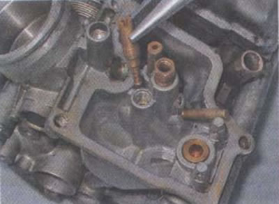
27. Using a 7 mm spanner, unscrew the spray tube of the main dosing system and remove it.
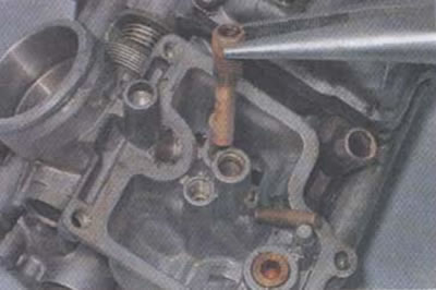
28. Using a Phillips screwdriver, unscrew the four screws securing the shut-off valve body.
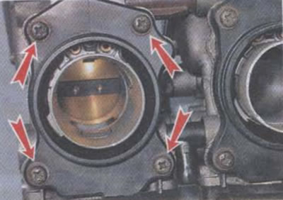
29. Remove the case.
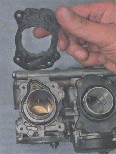
30. Remove the shut-off valve.

31. Remove the rubber gasket from the groove.
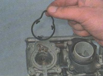
Attention! Rubber carburetor parts (shut-off needle, throttle valve diaphragm, rubber gaskets, rings, etc.) Under no circumstances should it be treated with carburetor cleaner or other strong solvents. When in contact with aggressive drugs, rubber products are irreversibly deformed and destroyed.
32. We wash all channels in the carburetor body, jets, covers, external and internal surfaces with carburetor cleaner (can also be washed with nitro thinner or acetone). The best results are achieved if, immediately after machining the part, (channel, plane) blow it out with compressed air.
Assembly
We assemble in the reverse order.
Attention! All parts must be thoroughly dried before assembly (preferably compressed air), to avoid contact of solvent residues with rubber parts. In addition, blowing with compressed air ensures that the parts and channels of the carburetor are clean from deposits, grains of sand and other foreign particles.
1. The screws of the float chamber cover and the membrane chamber are tightened crosswise to prevent the cover from tilting and breaking its tightness.
2. Before screwing in the screw «quality», assemble it: put a spring on the screw, then a steel washer, then a rubber ring (see photo, item 17).
3. Screw «quality» screw in until it stops and then back out two and a half turns. Further adjustment of the mixture quality is carried out based on the results of sea trials.
4. After disassembling and washing the carburetors, it is imperative to synchronize the operation of the carburetors (see «Carburettors - Timing»).
5. If, after the test trip, the carbon deposits on the candles are black, we wrap the screws «quality» on each carburetor 1/4 turn. If candles «white», back out the screws 1/4 turn. Adjusting the quality of the mixture is considered correct if the carbon deposits on the electrodes of the spark plugs have a light brownish or brick-red tint.
