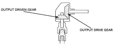
Removal
Separate the crankcase (page 11-4).
Remove the transmission (page 11-11).
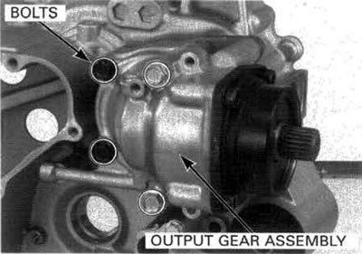
Remove the bolts and the output gear assembly.

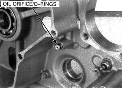
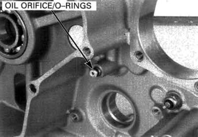
Remove the oil orifice and O-rings.
Backlash inspection/gear tooth contact pattern check
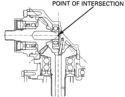
Perform the backlash inspection and contact pattern check whenever you replace the countershaft/output drive gear and output driven gear, bushings, bearing holder and gear case. The extension lines from the gear engagement surfaces should intersect at one point.
Backlash inspection
Clamp the output gear case in a vice that has soft jaws or use a shop towel.
Set the horizontal type dial indicator on the countershaft/output drive gear as shown.
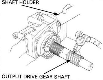
Hold the output driven gear shaft with the shaft holder and rotate the countershaft/output drive gear until gear slack is taken up.
Tools: Mainshaft holder 07923-6890101.
Turn the countershaft/output drive gear back and forth to read the backlash.
Standard: 0.08-0.23 mm (0.003-0.009 in).
Service limit: 0.40 mm (0.016 in).
Remove the dial indicator. Turn the countershaft/output drive gear 120° and measure the backlash. Repeat this procedure once more.
Compare the difference of the three measurements.
Backlash difference between measurements.
Service limit: 0.10 mm (0.004 in).
If the difference in measurements exceeds the limit, it indicates that the bearings must be replaced and reshimmed.
If the backlash is excessive, replace the counter-shaft/output drive gear adjustment shim with a thinner one.
If the backlash is too small, replace the counter-shaft/output drive gear adjustment shim with a thicker one.

Backlash is changed by about 0.06-0.07 mm (0.002-0.003 in) when shim thickness is changed by 0.10 mm (0.004 in).
Output drive gear adjustment shims:
- A: 0.40 mm (0.016 in)
- B: 0.45 mm (0.018 in)
- C: 0.50 mm (0.020 in) — Standard
- D: 0.55 mm (0.022 in)
- E: 0.60 mm (0.024 in)
To replace the shim, remove the countershaft/output drive gear and bearing holder as an assembly from the gear case.
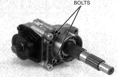
Replace the shim.
Coat a new gear holder О-ring with engine oil and install it into the gear holder groove.
Install the adjustment shim over the bearing holder.
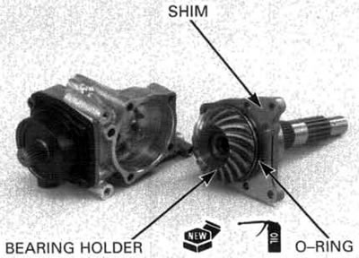
Set the bearing holder into the gear case.
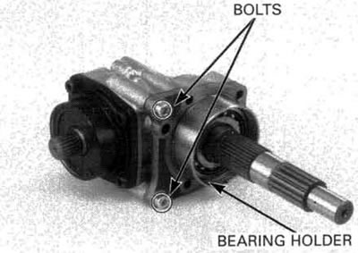
Apply engine oil to the gear holder bolt threads. Tighten the gear holder bolts to the specified torque.
Torque: 31 N·m (3.2 kgf·m, 23 lbf·ft).
After the backlash adjustments has been made, check the gear tooth contact pattern described next page.
Gear tooth contact pattern check
Description of the tooth:

Remove the countershaft/output drive gear from the gear case (page 11-19).
Apply Prussian Blue to the output driven gear teeth.
Reinstall the countershaft/output drive gear to the gear case.
Rotate the countershaft/output drive gear several times in the normal direction of rotation.
Remove the countershaft/output drive gear and check the gear tooth contact pattern as described following page.

Contact is normal if Prussian Blue is transferred to the approximate center of each tooth and slightly to the toe.
If the pattern is not correct, remove and replace the countershaft/output driven gear adjustment shim.
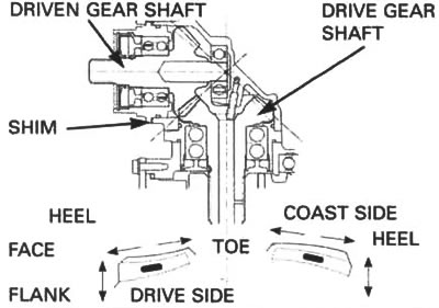
Replace the shim with a thinner one if the contact pattern is too high.

Replace the shim with a thicker one if the contact pattern is too low.

The pattern will shift about 1.5-2.0 mm (0.06-0.08 in) when the shim thickness is changed by 0.10 mm (0.04 in).
Output driven gear adjustment shims:
- A: 0.20 mm (0.008 in)
- B: 0.25 mm (0.010 in)
- C: 0.30 mm (0.012 in)
- D: 0.35 mm (0.014 in)
- E: 0.40 mm (0.016 in) — Standard
- F: 0.45 mm (0.018 in)
- G: 0.50 mm (0.020 in)
- H: 0.55 mm (0.022 in)
- I: 0.60 mm (0.024 in)
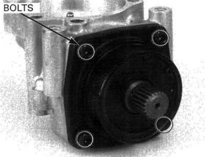
To replace the shim, remove the driven gear and bearing holder as an assembly from the gear case.
Replacing the shim.
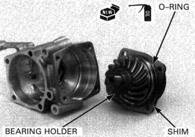
Coat a new gear holder О-ring with the engine oil and install it into the gear holder groove.
Install the adjustment shim over the bearing holder.
When the bearing, gear, holder and/or case have been replaced, use the 0.4 mm (0.016 in) shim for initial reference.
Align the bolt holes in the gear holder and shim, then install them into the gear case.
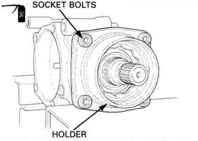
Apply engine oil to the threads and seating surface of the bearing holder socket bolts and tighten them.
Torque: 31 N·m (3.2 kgf·m, 23 lbf·ft).
Case bearing replacement
Remove the countershaft/output drive gear and bearing holder as an assembly (page 11-21).
Remove the driven gear and bearing holder as an assembly (page 11-23).
Heat the output gear case around the driven gear case bearing to 80°C (176°F).

Always wear insulated gloves when handling a heated gear case.
Remove the driven gear case bearing using the spe cial tools.
Tools:
- Remover handle 07736-3710100
- Bearing remover 07736-3710300
- Remover weight 07936-371020A or 07936-3710200
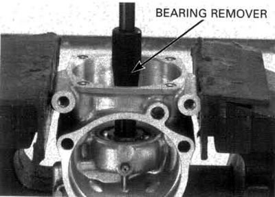
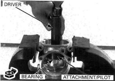
Drive a new bearing into the gear case using the special tools as shown.
Tools:
- Driver — 07749-0010000
- Attachment, 42x47 mm 07746-0010300
- Pilot, 17 mm 07746-0040400
Installation
Coat new orifice O-rings with engine oil and install them into the orifice grooves.
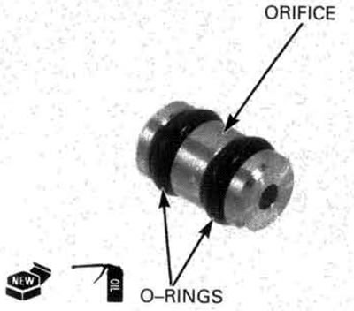
Install the orifice into the crankcase with the chamfered hole side facing the crankcase.
Coat a new О-ring with engine oil and install it into the groove in the bearing holder.
Be sure to install the dowel pin in the bearing holder and install the output gear assembly onto the left crankcase.

Install and tighten the gear case mounting bolts to the specified torque.
Torque: 31 N·m (3.2 kgf·m, 23 lbf·ft).
Install the transmission (page 11-16).
Assemble the crankcase (page 11-17).
