Crankshaft removal
Separate the crankshaft (page 11-4).
Remove the crankshaft from the left crankcase.

During crankshaft and connecting rod service, be careful not to damage the main journal or connecting rod bearing inserts.
Connecting rod removal
Before removing the connecting rods, check the big end side clearance.
Measure the clearance by inserting the feeler gauge between the crankshaft and connecting rod big end.
Service limit: 0.28 mm (0.011 in).

Remove the connecting bearing cap bolts and the bearing caps.
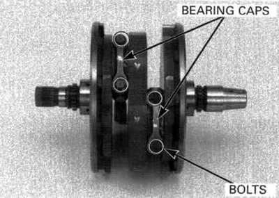
Tap the side of the cap lightly if the bearing cap is hard to remove.
Mark the rods, bearings and caps as you remove them to indicate the correct cylinder and position on the crankpins for reassembly.
For the connecting rod small end inspection, see page 9-7.

Crankshaft inspection
Crankshaft runout
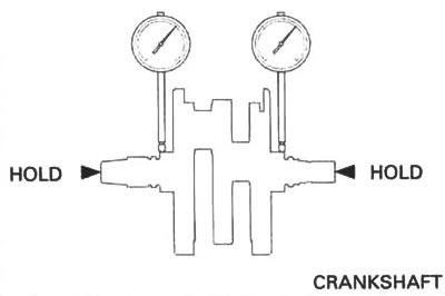
Place the crankshaft on a stand or V-blocks.
Set a dial indicator on the main journals.
Rotate the crankshaft two revolutions and read the runout.
Service limit: 0.05 mm (0.002 in).
Connecting rod bearing inspection
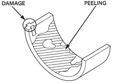
Inspect the bearing inserts for unusual wear, damage or peeling and replace as necessary.
Oil clearance inspection
Clean any oil from the bearing inserts and crankpins.
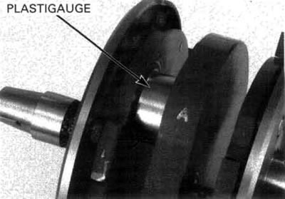
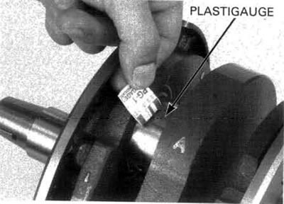
Put a strip of plastigauge lengthwise on each crankpin avoiding the oil hole.
Carefully install the connecting rods and bearing caps on the correct crankpins.
Apply engine oil to the threads and seating surfaces of the bearing cap bolts.
Install the bolts and tighten them evenly.
Torque: 49 N·m (5.0 kgf·m, 36 lbf·ft).
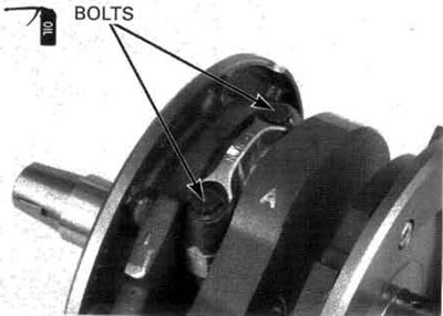
Do not rotate the crankshaft during inspection.
Remove the bearing caps and measure the compressed plastigauge at its widest point on each crankpin to determine the oil clearance.
Service limit: 0.070 mm (0.0028 in).
If the clearance exceeds the service limit, select the correct replacement bearings as follows.
Connecting rod bearing selection
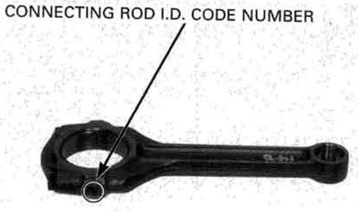
Record the connecting rod I.D. code number.
Number 1 or 2 on the connecting rod is the code for the connecting rod I.D.
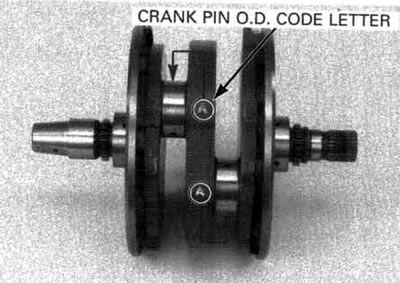
Record the crankpin O.D. code letter.
Mark A or В on each crank weight is the code for the crankpin O.D.
Cross reference the connecting rod and crankpin codes to determine the replacement bearing color code.
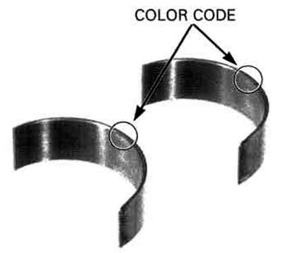
| Crankpin O.D. code | Connecting rod I.D. code | ||
| 55.000 - 55.008 mm (2.1654-2.1657 in) | 55.008 - 55.016 mm (2.1657-2.1660 in) | ||
| A | 51.982-51.990 mm (2.0465-2.0468 in) | Pink | Yellow |
| В | 51.974-51.982 mm (2.0462-2.0465 in) | Yellow | Green |
Connecting rod bearing thickness:
- Green: 1.495 - 1.499 mm (0.0589 - 0.0590 in): Thick
- Yellow: 1.491 - 1.495 mm (0.0587 - 0.0589 in)
- Pink: 1.487 - 1.491 mm (0.0585 - 0.0587 in): Thin
Main bearing inspection
Clean any oil from the bearings and crankshaft journal.
Measure and record the crank shaft main journal O.D.
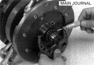
Measure and record the main bearing I.D. in the crankcase.
Calculate the clearance between the main journal and main bearing.
Service limit: 0.068 mm (0.0027 in).
If the oil clearance exceeds the service limit, replace the crankcase.
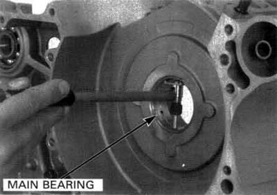
Be careful not to damage the inside of the bearing during inspection.
Connecting rod selection
An alphabetical weight code is stamped on the connecting rod.
If a connecting rod requires replacement, you should select a rod with the same weight code as the original. But if that is unavailable, you may use one of the others specified in the following chart.
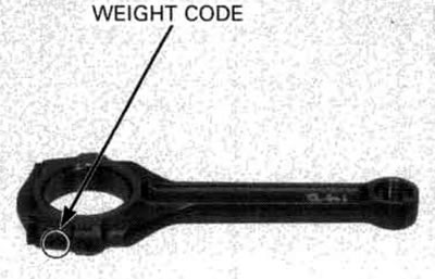
The "O" mark in the table indicates that mating is possible in the crossed codes.
| FRONT ROD CODE | REAR ROD CODE | |||
| A | B | C | D | |
| A | O | O | ||
| В | O | O | O | |
| C | O | O | O | |
| D | O | O | ||
Connecting rod installation
Wipe any oil from the connecting rod, cap and bearing inserts.
Install the bearing inserts on the connecting rods and caps by aligning the tab with the groove.
Apply molybdnum oil solution to the thrust surface of the bearings.

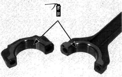
Install the rods and caps on the crankshaft by aligning the I.D. code on the rod and cap. Be sure each part is installed in its original position, as noted during removal.
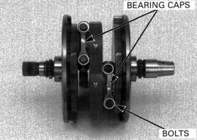
Apply engine oil to the bearing cap bolt threads and tighten the them in two or more steps alternately.
Torque: 49 N·m (5.0 kgf·m, 36 lbf·ft).
After tightening the bolts, check that the connecting rods move freely without binding.
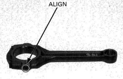
Apply molybdenum oil solution to the main bearing inserts and install the crankshaft into the left crankcase.
Assemble the crankcase (page 11-17).

