
Removal
Separate the crankcase (page 11-4).
Remove the oil pump (page 4-3).
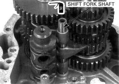
Pull the shift fork shaft up and remove it from the shift forks.
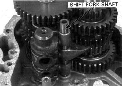
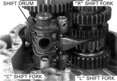
Remove the shift drum and shift forks.

Remove the washer, C1 gear, C4 gear, collars and needle bearing from the countershaft.

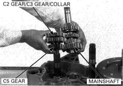
Remove the C2 gear, C3 gear, C5 gear and collar from the countershaft.
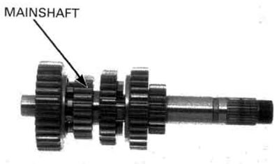
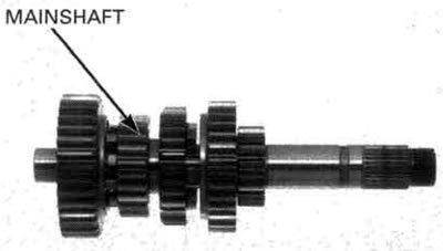
Remove the mainshaft as an assembly.

Remove the output gear assembly (page 11-19).
Disassembly
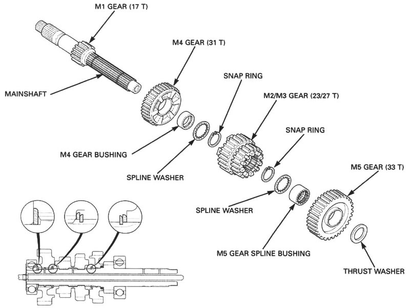
Disassemble the mainshaft.
Inspection
Gears
Check the gear dogs, dog hole and teeth for damage or excessive wear.
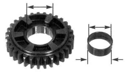
Measure the I.D. of each gear.
Service limits:
- M4, M5 gears: 31.035 mm (1.2218 in)
- C1 gear: 30.035 mm (1.1825 in)
- C2/C3 gears: 33.035 mm (1.3006 in)
Bushing
Check the bushings for wear or damage.
Measure the O.D. of each bushing.

Service limits:
- M4, M5 gear bushings: 30.94 mm (1.218 in)
- C1 gear bushing: 25.977 mm (1.0227 in)
- C2/C3 gear bushing: 32.94 mm (1.297 in)
Measure the I.D. of each bushing.
Service limits:
- M4 gear bushing: 28.03 mm (1.104 in)
- C1 gear bushing: 22.170 mm (0.8728 in)
- C2/C3 gear bushing: 30.050 mm (1.1831 in)
Mainshaft/countershaft
Check the spline grooves and sliding surfaces for abnormal wear or damage.
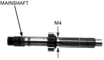
Measure the O.D. of the mainshaft and countershaft at the gear and bushing sliding areas.
Service limits:
- Mainshaft
- (at M4 gear): 27.940 mm (1.1000 in)
- (at clutch outer guide): 27.970 mm (1.1012 in)
- Countershaft
- (at C1 gear): 21.97 mm (0.865 in)
- (at C2/C3 gear): 29.94 mm (1.179 in)
Calculate the gear-to-bushing and bushing-to-shaft clearance.
Service limits:
- Gear-to-bushing
- (M4, M5): 0.095 mm (0.0037 in)
- (C2/C3): 0.095 mm (0.0037 in)
- Bushing-to-shaft
- (M4) 0.067 mm (0.0026 in)
- (C1) 0.190 mm (0.0075 in)
- (C2/C3) 0.091 mm (0.0036 in)
Shift fork
Check for deformation or abnormal wear.
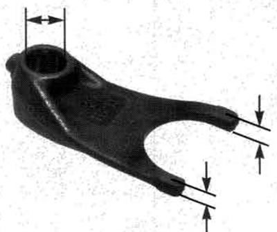
Measure the shift fork claw thickness.
Service limit: 5.83 mm (0.230 in).
Measure the shift fork I.D.
Service limit: 14.04 mm (0.553 in).
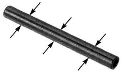
Shift fork shaft
Check for bends, abnormal wear or damage.
Measure the shift fork shaft O.D.
Service limit: 13.956 mm (0.5494 in).
Shift drum
Inspect the shift drum end for scoring, scratches, or evidence of insufficient lubrication.
Check the shift drum grooves for abnormal wear or damage.

Shift drum bearing and journal
Check the shift drum bearing on the left crankcase for excessive play or damage.
Check the shift drum journal in the left crankcase for excessive wear or damage.
Assembly
Clean all parts in solvent.
Apply molybdenum oil solution to the bushing sliding surface and shift fork grooves to ensure initial lubrication.
Apply engine oil to every gear to ensure initial lubrication.
Assemble all parts into their original positions.
Check the gears for smooth movement or rotation on the shaft.
Install the washers and snap rings with the chamfered edges facing the thrust road side. Do not reuse a worn snap ring which could easily spin in the groove.
Check that the snap rings are seated in the grooves and align their end gaps with the grooves of the spline.
Mainshaft
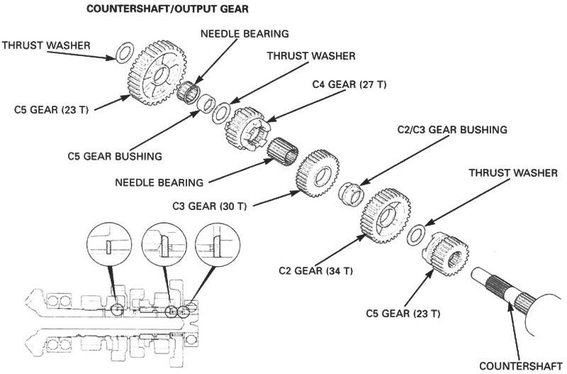
Countershaft/output gear
Installation
Install the output gear assembly (page 11-24).
Install the mainshaft to the left crankcase as an assembly.
Install the collar, C5 gear, C3 gear, C2 gear to the countershaft.
Install the needle bearing, collars, C4 gear, C1 gear to the countershaft.
Check the mainshaft and countershaft installation.

Install the shift forks into the shifter gear grooves with the marked side facing up (right crankcase side).
Install the shift drum by aligning the shift fork guide pins with the shift drum guide grooves.

Apply engine oil to the shift fork shaft and install it through the shift forks into the left crankcase.
After installing, check for smooth transmission operation.
Assemble the crankcase (see below).