

If any are loose, remove them, clean their threads with contact cleaner, then install them using locking agent.
After installation, be sure to measure the distance from the top of each stud to the final gear case surface as shown.
If the universal joint was removed, install the universal joint and swingarm (page 14-14).
Drive shaft assembly/installation
Install a new stopper ring.
Install the spring and new oil seal and pack 0.5 g (0.02 oz) of molybdenum disulfide grease into seal lip cavity.
Make sure the stopper ring is seated properly by pulling on the drive shaft lightly. Be careful not to damage the drive shaft oil seal.
Pack 2 g (0.08 oz) of molybdenum disulfide grease into the pinion joint spline.
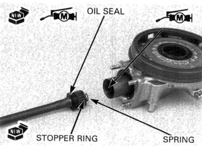
Install the drive shaft into the pinion joint until the stopper ring seats in the pinion joint spline groove.
Pack 1 g (0.04 oz) of molybdenum disulfide grease into the drive shaft spline.
Insert the final drive assembly into the swingarm and align the splines with the universal joint by holding the swingarm.
Install the gear case mounting nuts and shock absorber lower mounting bolt and tighten them to the specified torque.
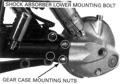
Torque:
- Final gear case mounting nut: 64 N·m (6.5 kgf·m, 47 lbf·ft)
- Rear shock absorber mounting bolt: 26 N·m (2.7 kgf·m, 20 lbf·ft)
Install the rear wheel (page 14-10).
Fill the gear case with the recommended final drive oil (page 3-18).
Oil capacity: 150 cm3 (5.1 US oz, 5.3 Imp oz) at disassembly.