Vehicle-down sensor removal
Remove:
- Tool Box (see Tool box removal in the Frame chapter)
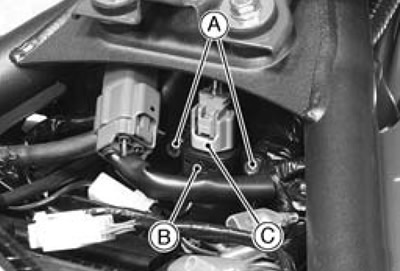
- Bolts [A]
- Vehicle-down Sensor [B]
- Connector [C] (disconnect)
Vehicle-down sensor installation
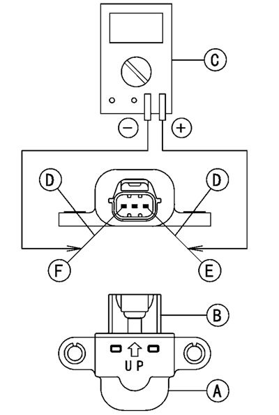
Install the vehicle-down sensor [A] in the original position. The arrow mark [B] on the sensor must be on the rear and point upward.
Do not install the sensor upside down.
Tighten: Front [D].
- Torque-Vehicle-down Sensor Bolts [C]: 4.9 N·m (0.50 kgf·m 43 ft·lb)

Warning! Incorrect installation of the vehicle-down sensor could cause sudden loss of engine power. The rider could lose balance during certain riding situations, like leaning over in a turn, with the potential for an accident resulting in injury or death. Ensure that the down sensor is held in place by its bolt as shown.
Vehicle-down sensor inspection
Note. Be sure the battery is fully charged.
Take out the vehicle-down sensor [A] (see Vehicle-down sensor removal). Do not disconnect the connector [B].
Connect a digital volt meter [C] to the connector, using two needle adapters [D].
- Special Tool - Needle Adapter Set: 57001-1457
Turn the ignition switch ON, and measure the power source voltage with the connector joined.
Vehicle-down sensor power source voltage connections to sensor:
- Meter (+) → BL lead [E]
- Meter (-) → BR/BK lead [F]
Standard: 4.75-5.25 V DC
Turn the ignition switch OFF.
★ If the reading of input voltage is less than the standard, check the ECU for its ground, power supply and wiring shorted.
★ If the power source is normal, check the output voltage of the sensor.
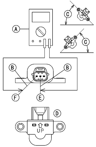
Connect a digital volt meter [A] to the connector, using two needle adapters [B].
Turn the ignition switch ON, and measure the output voltage with the connector joined.
Tilt the sensor (40-50°) or more [C] right or left, then hold the sensor almost vertical [D] with the arrow mark pointed up, and measure the output voltage.
Vehicle-down sensor output voltage connections to sensor:
- Meter (+) → Y/G lead [E]
- Meter (-) → BR/BK lead [F]
Standard:
- with sensor tilted 40-50° or more right or left: 0.65-1.35 V
- with sensor arrow mark pointed up: 3.55-4.45 V
Note. If you need to test again, turn the ignition switch OFF, and then ON.
Turn the ignition switch OFF.
Remove the needle adapters, and apply silicone sealant to the seals of the connector for waterproofing.
- Silicone Sealant (Kawasaki Bond: 56019-120) - Seals of Vehicle-down Sensor Connector
★ If the output voltage is out of the specified, replace the vehicle-down sensor.
★ If the output voltage is normal, the wiring is suspect. Check the wiring.
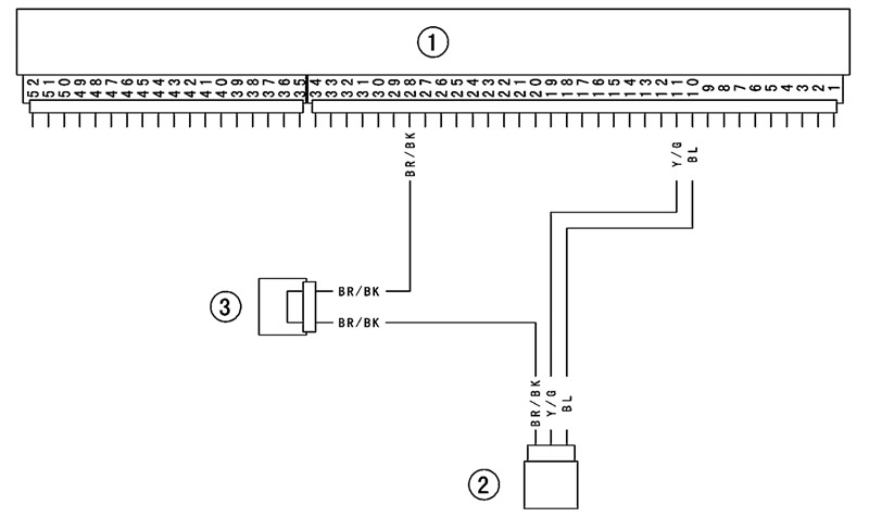
Vehicle-down sensor circuit (other than Europe models)
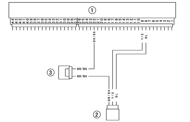
Vehicle-down sensor circuit (Europe models)