
Speed sensor removal
Refer to the Speed sensor removal in the Electrical System chapter.
Speed sensor installation
Refer to the Speed sensor installation in the Electrical System chapter.
Speed sensor inspection
Refer to the Speed sensor inspection in the Electrical System chapter.
Input voltage inspection
Note. Be sure the battery is fully charged.
Turn the ignition switch OFF.
Remove the speed sensor (see Speed sensor removal in the Electrical System chapter).
Connect the harness adapter [A] between the harness connector [B] and speed sensor connector [C].
- Special Tool - Speed Sensor Measuring Adapter: 57001-1667
Reinstall the speed sensor with the harness adapter connected.
Connect a digital meter [D] to the connector harness adapter leads.
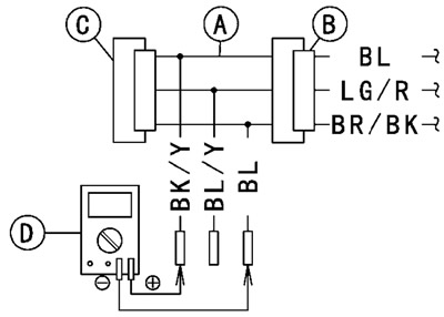
Speed sensor input voltage connections to adapter:
- Meter (+) → BK/Y (sensor BL) lead
- Meter (-) → BL (sensor BR/BK) lead

Measure the input voltage with the engine stopped, and with the connectors joined.
Turn the ignition switch ON.
Input voltage at sensor:
- Standard: 4.75-5.25 V DC
★ If the reading is out of the range, check the wiring.
★ If the reading is good, check the output voltage.
Turn the ignition switch OFF.
Output voltage inspection
Before this inspection, inspect the input voltage (see Input voltage inspection in the Speed Sensor section).
Note. Be sure the battery is fully charged.
Turn the ignition switch OFF.
Using the jack, raise the rear wheel off the ground.
- Special Tool - Jack: 57001-1238
Remove the speed sensor (see Speed sensor removal in the Electrical System chapter).
Connect the harness adapter [A] between the harness connector [B] and speed sensor connector [C].
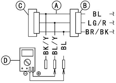
- Special Tool - Speed Sensor Measuring Adapter: 57001-1667
Reinstall the speed sensor with the harness adapter connected.
Connect a digital meter [D] to the connector harness adapter leads.
Speed sensor output voltage connections to adapter:
- Meter (+) → BL/Y (sensor LG/R) lead
- Meter (-) → BL (sensor BR/BK) lead

Measure the output voltage with the engine stopped, and with the connectors joined.
Turn the ignition switch ON.
Output voltage at sensor:
- Standard: DC 0.05-0.09 V or DC 4.5-4.9 V
Rotate the rear wheel by hand, confirm the output voltage will be raise or lower.
★ If the reading is out of the range, replace the speed sensor (see Switch and Sensors section in the Electrical System chapter) and check the wiring to ECU (see next diagram).
★ If the reading, speed sensor and wiring are good, replace the ECU (see ECU section).
Turn the ignition switch OFF.
Speed sensor circuit (other than Europe models)

Speed sensor circuit (Europe models)

1. ECU; 2. Meter Unit; 3. Joint Connector B; 4. Speed Sensor