Removal
1. Remove the rider's seat
2. Disconnect the battery, negative (black) lead first.
3. Remove the throttle bodies as described on page 11.122.
4. Remove the nut, metal washer and plastic washer attaching the idle control stepper arm to the idle speed control lever.
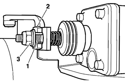
1. Idle control stepper arm; 2. Idle speed control lever; 3. Nut etc.
5. Using the linkage, rather than the butterfly plates, fully open the primary throttle by hand.
6. Turn the idle speed control lever away from the stepper arm and remove the plastic collar and spring.
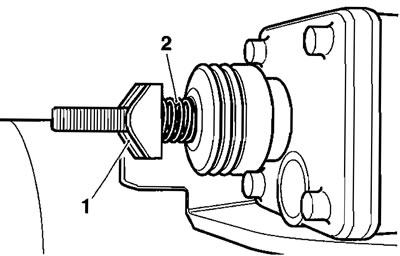
1. Collar; 2. Spring
7. Remove the two screws securing the idle speed control stepper motor to its bracket, then remove the stepper motor.
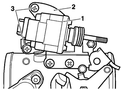
1. Idle speed control stepper motor; 2. Bracket; 3. Fixings
Installation
1. Turn the idle speed control lever until it the stepper motor can be fitted without obstruction of any kind.
2. Locate the stepper motor to its bracket and tighten the fixings to 3.5 Nm.
3. Locate the spring and plastic collar.

1. Collar; 2. Spring
4. Fit the plastic washer through the lever then fit the metal washer and nut.
5. Refit the throttle bodies as described earlier in this section, but do not fit the intake cover.
6. Temporarily reconnect the battery, positive (red) lead first.
7. Turn the ignition to the ON position.
8. Connect the service diagnostic tool and scroll through to, and select the "ADJUST TUNE" option.
9. At the next screen, align the cursor with ISC* STEPPER RENEW (see below) then press the validation key which is marked "*".
* ISC = Idle Speed Control
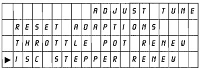
10. On pressing the validation key, the diagnostic tool will send a command that drives the primary throttle to the fully closed position. The tool will also display the voltage reading coming from the throttle position sensor which will be needed for a check/adjustment made later in the process.

11. Tighten the stepper arm nut until a clearance of 0.5 mm can be measured between the idle speed control cam and the throttle roller (see the diagram below).
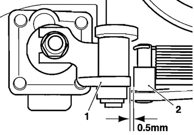
1. Idle speed control cam; 2. Throttle roller
12. Check the voltage reading on the tool. If the reading is 0.6 volts±0.02 volts, MAKE A NOTE OF THE EXACT VOLTAGE READING then proceed to step 18. If the reading is not within this tolerance band, adjustment must be made as described in steps 13 to 15.
13. Slacken the retaining screw on the primary throttle position sensor.
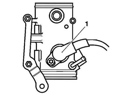
1. Primary throttle position sensor
14. Gently turn the primary throttle position sensor until the voltage reading on the tool shows 0.6 volts±0.02 volts. MAKE A NOTE OF THE EXACT VOLTAGE READING.
15. Tighten the sensor retaining screw to 3.5 Nm and recheck the voltage reading shown on the tool. Repeat the adjustment if the reading is outside the specified range, NOTING THE FINAL VOLTAGE READING IF ADJUSTMENT IS MADE.
16. Press the validation key marked to progress to the next adjustment.
17. On pressing the validation key, the diagnostic tool will send a command that drives the primary throttle to the fully open position. The tool will also display the voltage reading coming from the throttle position sensor.
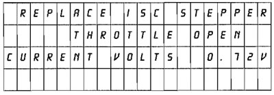
18. With the stepper fully opened, check the voltage shown on the tool and adjust the nut on the top of the stepper arm until the tool shows a voltage equivalent to X+0.12 (±0.05V) where X= the voltage measured in step 12 (or 15 if readjusted).
For example, if the voltage measured was 0.6 volts, then the correct setting would be 0.715-0.725 volts.

1. Adjustment nut
19. Press the validation key marked to fully close the idle speed control stepper motor. After a minimum of 15 seconds (the tool will not allow further actions to take place during this period), press the validation key again to return the ECM to normal control.
20. Turn the ignition to the OFF position.
21. Disconnect the battery, negative (black) lead first.
22. Check and adjust the throttle cable settings as described on page 11.119).
Warning! Operation of the motorcycle with an incorrectly adjusted throttle position sensor, or a throttle position sensor that causes the throttle to stick could result in loss of throttle control. Loss of throttle control could result in loss of control of the motorcycle and an accident.
Warning! Operation of the motorcycle with an incorrectly adjusted, incorrectly routed or damaged throttle cable could interfere with the operation of the brakes, clutch or the throttle itself. Any of these conditions could result in loss of control of the motorcycle and an accident.
Warning! Move the handlebars to left and right full lock while checking that cables and harnesses do not bind. A cable or harness which binds will restrict the steering and may cause loss of control and an accident.
23. Support the tank, remove and stow the tank prop, then lower the tank to the frame and secure it as described on page 11.99.
24. Refit the intake cover as described on page 11.99.
25. Reconnect the battery, positive (red) lead first.
26. Refit the rider's seat.
