
Removal
Warning! If the engine has recently been running, the exhaust components may be hot to the touch. Contact with the hot components may cause damage to exposed skin. To avoid skin damage, always allow the hot parts to cool before working on the exhaust system.
Note: In the following procedures, the term catalyst box refers to the rectangular chamber to which the silencers are attached. In many countries, catalytic converters are fitted inside this component. However, in certain countries (depending on their exhaust emission regulation) no catalyst will be fitted.
Note: Always note the position and orientation of exhaust clamps prior to releasing them, and return them to the noted position and orientation on assembly.
1. Remove the catalyst box/silencer heat shields.
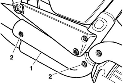
1. Heat shield; 2. Heat shield fixings
2. Disconnect the battery, negative (black) lead first.
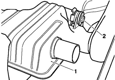
3. Release the clamps securing the silencers to the catalyst box.
1. Silencer clamp fixings; 2. Catalyst box
4. Release the fixing securing the silencers to their brackets.
1. Silencer bracket; 2. Fixings
5. Detach the silencers from the catalyst box.
6. Collect the silencer gaskets.
7. Disconnect the oxygen sensor connection from the wiring harness.
8. Remove the upper heat shields from the exhaust headers.
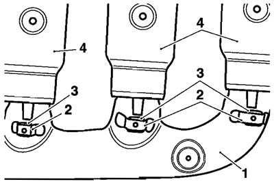
9. Remove the lower heat shield from the headers. After removal, collect the small rubber isolators from the brackets on the inner heat shield (or on a tag on the end of the upper shields, depending on where they are retained).
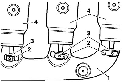
1. Lower heat shield; 2. Isolator brackets; 3. Isolators; 4. Upper heat shields
10. Release the clamp securing the headers to the catalyst box.
11. At the cylinder head, release the nuts securing the header pipes to the head.

1. Header downpipe; 2. Fixings
12. Detach and remove the header assembly.
13. Collect the header gaskets from the head and catalyst box entry.
Note: The catalyst box is secured to the frame by a single fixing on the right hand side, and is located on two studs on the left hand side.
Caution! The catalyst box is located very close to the starter cables. Ensure you have disconnected the battery. Otherwise an electrical short may occur.
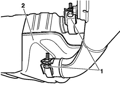
14. Release the fixing securing the catalyst box to the frame.
1. Catalyst box; 2. Fixing
15. Detach the catalyst box by easing it to the right hand side of the motorcycle.
Note: Catalyst box mounting grommets may remain in the catalyst box or may adhere to the mounting studs on removal of the catalyst box.
16. Collect the catalyst box mounting grommets.
Installation
1. Check and if necessary renew the catalyst mounting box grommets. Fit the mounting grommets to the mounting points on the catalyst box.
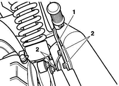
2. Locate the catalyst box to the mounting studs on the right hand side. Insert the flanged sleeve into the right hand grommet and then fit the bolt and washer to retain the assembly.
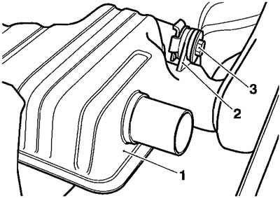
1. Catalyst box; 2. Right hand mounting; 3. Bolt/washer
3. Fit new gaskets to the cylinder head ports.

1. Cylinder head ports; 2. Gaskets
Note: To retain the gaskets during assembly, apply a smear of grease or petroleum jelly to the gasket faces in the head.
4. Apply "Copperslip" grease to the header studs on the cylinder head.
5. Fit a new gasket to the header entry to the catalyst box and position the ciamp over the joint.
6. Locate the headers to the catalyst box, then align to the cylinder head. Ensure the gaskets do not become displaced during assembly.
7. Tighten all the header nuts to 19 Nm.
8. Tighten the catalyst box mounting bolt to 27 Nm.
9. Tighten the header to catalyst box clamp bolt to 22 Nm.
10. If removed, fit the oxygen sensor and tighten it to 40 Nm.
11. Reconnect the oxygen sensor to the main wiring harness.
12. Fit the isolator rubbers to the tags at the bottom of the upper heat shields.
13. Position the lower heat shields to the header pipes.
14. Fit the lower heat shield screws; spring washers and flat washers, then tighten the screws to 7 Nm.
15. Position each of the upper heat shields to the headers, engaging the isolators in the corresponding brackets in the lower inner heat shield.
1. Lower heat shield; 2. Bracket; 3. Isolator; 4. Upper heat shields
16. Fit the upper heat shield screws; spring washers and fiat washers, then tighten the screws to 7 Nm.
17. Fit new gaskets to each silencer.
18. Position the silencer clamps to each catalyst box exit.
19. Fit each silencer to the catalyst box and position to the silencer brackets.
20. Engage the mounting bracket fixings, finger tight.
21. Tighten each silencer bracket fixing to 15 Nm.
22. Tighten each silencer clamp to 22 Nm.
23. Position the heat shields to the silencers.
24. Fit the silencer heat shield screws; spring washers and fiat washers, then tighten the screws to 7 Nm.
25. Reconnect the battery, positive (red) lead first.