Removal
1. Remove the rider's seat.
2. Disconnect the battery negative (black) lead first.
3. Raise and prop the fuel tank as described on page 11.98.
4. Noting their orientation, release the three clips securing the intake plenum to the throttle bodies.
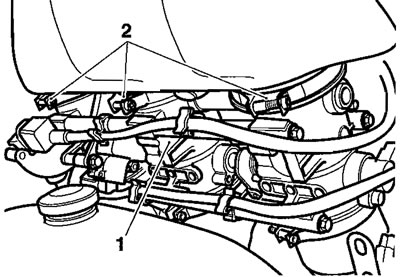
1. Throttle bodies; 2. Clips
5. Release the two clips securing the intake plenum to the intake duct.
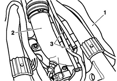
1. Intake plenum; 2. Intake duct; 3. Clips
6. Carefully detach the intake plenum from the throttle bodies and intake duct. Place the intake plenum aside.
7. Noting its orientation, release the clip securing the intake hose to the intake duct.

1. Intake hose; 2. Intake duct; 3. Clip
8. Disconnect the manifold absolute pressure (MAP) and air temperature sensors from the wiring harness.

1. MAP sensor; 2. Air temperature sensor; 3. Connectors
9. Release the fixing securing the intake duct to its bracket. Remove the duct.
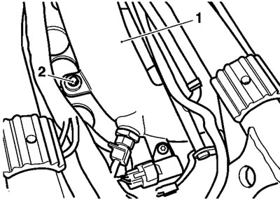
1. Intake duct; 2. Fixing
10. If fitted, disconnect the small diameter evaporative system return tubes from the base of each throttle.
11. Disconnect throttle cables from throttle linkage as described on page 11.117.
12. Disconnect the electrical multi-plugs from:
- both of the throttle position sensors,
- the idle speed control stepper motor,
- the second throttle stepper motor,
- the injectors.
13. Detach the MAP sensor hoses from the four-way connector above the cam cover.
14. Release the two fixings securing the throttle bodies to the transition piece brackets.
15. Release the clips securing the throttle bodies to the transition pieces.
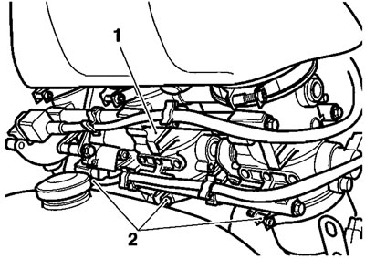
1. Throttle body; 2. Clips
16. Raise the throttle bodies from the transition pieces and, feeding the fuel hose and wiring past the frame etc. remove the throttle bodies from the engine.
17. Remove the screws securing each transition piece to the cylinder head.
18. Remove the transition pieces and discard the 'O'-ring seals.
Note: Collect the throttle body brackets from the transition pieces for throttles 1 and 3.
19. Cover the inlet ports to prevent the ingress of dirt and other objects.
Installation
1. Remove the covers from the inlet ports and ensure that the mating faces are clean.
2. Locate new O-ring seals to the transition pieces.
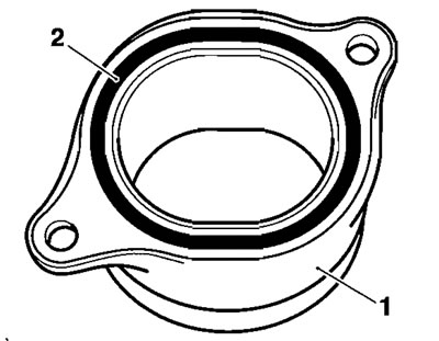
1. Transition piece; 2. O-ring
3. Position each transition piece to the cylinder head, together with the brackets on cylinders 1 and 3. Tighten the screws to 12 Nm.
4. Position the throttle body assembly to the transition pieces, feeding the MAP sensor hoses, fuel hoses and sensor/motor cables through the frame. Push each throttle body into its respective transition piece. Ensure that each throttle body is fully seated.
5. Tighten the throttle body clips, with the screw heads all facing rearwards, to 1.5 Nm.
Note: Ensure the throttles seat correctly in the transition pieces and seal each throttle through 360 degrees.
6. Fit the throttle body to transition piece bracket fixings, tightening them to 6 Nm.
7. On California models, reconnect the evaporative return hoses to each throttle body.
8. Connect the multi-plugs to:
- both of the throttle position sensors.
- the idle speed control stepper motor.
- the second throttle stepper motor.
- each injector.
9. Connect and adjust the throttle cables as described on page 11.118.
Warning!
- Ensure that all the adjuster locknuts of both cables are correctly seated and tightened as a sticking throttle could result from a loose locknut.
- An incorrectly adjusted, sticking or stuck throttle will lead to loss of motorcycle control and an accident.
Warning! Operation of the motorcycle with an incorrectly adjusted, incorrectly routed or damaged throttle cable could interfere with the operation of the brakes, clutch or the throttle itself. Any of these conditions could result in loss of control of the motorcycle and an accident.
Warning! Move the handlebars to left and right full lock while checking that cables and harnesses do not bind. A cable or harness that binds will restrict the steering and may cause loss of control and an accident.
10. Feed the MAP sensor hoses back to the four-way connector and reconnect them.
11. Position the intake duct to its bracket and also to the intake hose. Secure the intake hose with its clip.
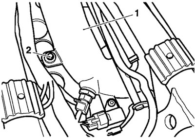
1. Intake duct; 2. Fixing
Caution! Ensure the hose is positively located to the duct and is retained by the clip through its full circumference. Rectify if necessary as poor engine performance and damage may result from poor hose sealing.
12. Refit the intake plenum to the throttle bodies and intake duct. Tighten all hose clips.
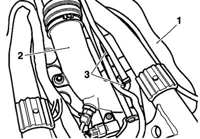
1. Intake plenum; 2. Intake duct; 3. Clips
13. Reconnect the MAP and air temperature sensor connections.
Caution! Ensure the plenum is positively located to the throttle bodies and intake duct and is retained by the clips through their full circumference. Rectify if necessary as poor engine performance and damage may result from poor plenum/duct sealing.
14. Support the tank, remove and stow the tank prop, then lower the tank to the frame and secure it as described on page 11.99.
15. Refit the intake cover as described on page 11.99.
16. Reconnect the battery, positive (red) lead first.
17. Refit the rider's seat.
