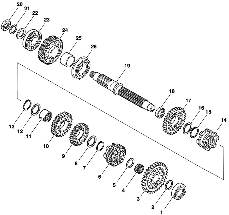
1. Ball bearing; 2. Thrust washer; 3. First gear; 4. Needle roller bearing; 5. Thrust washer; 6. Fifth gear; 7. Circlip; 8. Thrust washer; 9. Fourth gear; 10. Third gear; 11. Splined bush; 12. Thrust washer; 13. Circlip; 14. Dog ring; 15. Circlip; 16. Thrust washer; 17. Second gear; 18. Second gear bush; 19. Output shaft; 20. Nut; 21. "C" washer; 22. Flat washer; 23. Ball bearing; 24. Output gear; 25. Spacer; 26. Ball bearing
Disassembly
Note: All numbers given within brackets in the procedure below, refer directly to the numbered items in the above diagram.
Make a note or mark the orientation of all parts prior to removal.
1. Remove the ball bearing (1) and washer (2).
2. Remove first gear (3) and its needle roller bearing (4).
3. Remove the first gear thrust washer (5).
4. Remove fifth gear (6), revealing a circlip (7) that secures fourth and third gears.
5. Remove the circlip (7).
6. Slide off the thrust washer (8) from in front of fourth gear (9), then slide off fourth gear.
7. Slide off third gear (10), the splined third/fourth gear bush (11) and the thrust washer (12).
8. Remove the circlip (13) from in front of the splined dog ring (14).
9. Slide off the splined dog ring (14).
10. Remove the circlip (15) from in front of second gear (17).
11. Slide off the second gear thrust washer (16), then second gear (17) and its bush (18).
12. Working now from the other end of the shaft, remove the large nut (20) Bellville washer (21) and flat washer (22).
13. Slide off the ball bearing (23), output gear (24) and spacer (25).
Never wear loose clothing, which could become trapped in the press and cause crushing injury to the hand, arms or other parts of the anatomy.
14. Place the shaft (19) in a press with the threaded end of the shaft facing the press ram. Support the centre bearing (26) on press bars.

1. Press; 2. Output shaft; 3. Centre bearing; 15. Press the shaft through the bearing.
Inspection
1. Examine all gears, bearings and bushes and thrust washers for damage, distortion, chipped teeth and wear beyond the service limits. Replace all suspect components and always use new circlips to assemble the shaft.
Assembly
Note: Lubricate each gear, thrust washer and bush with clean engine oil during assembly.
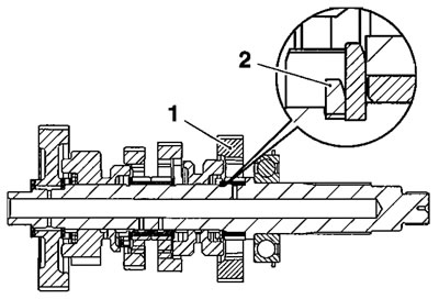
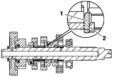
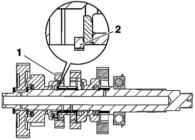
Note: The circlips used on the output shaft have a flat side and an angled side. Illustrations throughout the assembly text indicate which orientation of each circlip is correct.
Caution! Bushes with oil holes must always be MISALIGNED with the corresponding oil holes in the output shaft. Reduced oil pressure and gear lubrication may result from alignment of the oil holes, which would cause premature wear of engine and transmission components.
Warning!
- When using a press, always wear overalls, eye face and hand protection. Objects such as bearings frequently break-up under load and the debris caused during break-up may cause damage and injury to unprotected parts of the body.
- Never wear loose clothing, which could become trapped in the press and cause crushing injury to the hand, arms or other parts of the anatomy.
1. Place the centre output shaft bearing (26) on press bars, ensuring that the press bars support the inner race of the bearing and the circlip groove on the outer race is nearest to the press bars.

1. Output shaft; 2. Bearing; 3. Circlip groove; 4. Press bars
2. Locate the output shaft (19) to the bearing, with the threaded end pointing through the bearing (i.e. away from the press).
3. Press the output shaft through the bearing until the shoulder in the centre of the shaft contacts the bearing face.
4. Fit the spacer (25) to the shaft, then slide on the output gear (24).
5. Fit the bearing (24) to the shaft and retain with the flat washer (22), Bellville washer (21) and nut (20). Tighten the nut to 145 Nm.
6. Working from the other end of the shaft, slide on the second gear bush (18).
7. Fit second gear (17) and thrust washer (16).
8. Fit a new circlip (15), orientating the circlip as shown below.

1. Second gear; 2. Circlip
9. Fit the splined dog ring (14) to the shaft.
10. Retain the dog ring with a new circlip (13), orientating the circlip as shown below.

1. Dog ring; 2. Circlip
11. Fit the thrust washer (12) and splined bush (11).
12. Slide third and fourth gears (10 and 9) onto the splined bush.
13. Fit the thrust washer (8), then a new circlip (7), orientating the circlip as shown below.

1. Third/fourth gear; 2. Circlip
14. Fit fifth gear (6) to the shaft, followed by the thrust washer (5).
15. To complete assembly of the output shaft, fit the needle roller bearing (4), first gear (3), thrust washer (2) and bearing (1).
