
Warning!
- Make sure the motorcycle is stabilised and adequately supported.
- A correctly supported motorcycle will help prevent it from falling.
- An unstable motorcycle may fall, causing injury to the operator or damage to the motorcycle.
1. Fit the right hand switch housing retaining clip to the handlebar as noted during removal.
2. Slide the right hand switch housing onto the handlebar and over the retaining clip until it locks into position.
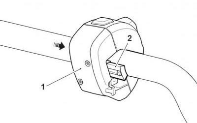
1. Right hand switch housing; 2. Retaining clip
3. Slide the twist grip position sensor onto the right hand side of the handlebar.
4. Locate the handlebar onto the risers. Fit the handlebar clamp and fixings.
5. Align the handlebar alignment mark with the front split line of the right hand riser.
6. Tighten the front clamp bolts to 26 Nm, then the rears.
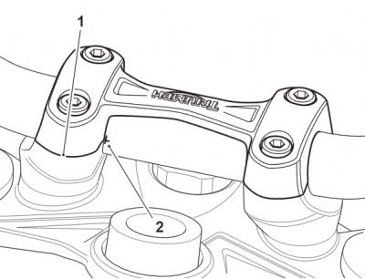
1. Right hand split line; 2. Alignment mark
7. Connect the right hand switch housing electrical connectors and secure the wiring harness to the switch housing using a new cable tie.
8. Fit the retaining clip and left hand switch housing to the handle bar as described in steps 1 and 2.
Note:
- The left hand switch housing electrical connections are recessed into the switch housing body.
- When inserting the connectors, carefully locate the connectors into their sockets, then use a suitable flat ended pin punch to push the connectors fully home. An audible click can be heard when the connectors are fully inserted.
- Do not use sharp tools, such as a flat bladed screw driver, to insert the connectors.

1. Switch housing electrical connectors
9. Connect the left hand switch housing electrical connectors and secure the wiring harness to the switch housing using a new cable tie.
10. Fit the left hand handlebar grip and secure with the fixings and washers. Tighten the fixings to 3 Nm.
11. Position the clutch lever to the handlebar. Fit the clamp (UP arrow pointing upwards) and clamp fixings.
12. Align the split line of the clutch lever with the alignment mark on the upper surface of the handlebar, then tighten the clamp fixings, upper first, to 12 Nm.
13. Fit the clutch switch to the clutch lever assembly and tighten its fixing to 2 Nm.
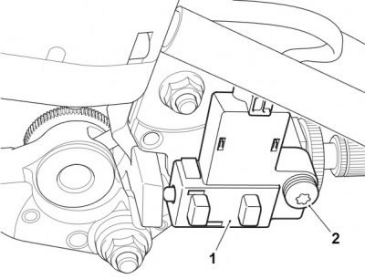
1. Clutch switch; 2. Fixing
14. Position the front brake master cylinder assembly to the handlebar. Fit the clamp (Up arrow pointing upwards) and clamp fixings.
15. Align the split line of the master cylinder clamp to the alignment mark on the upper surface of the handlebar and tighten the clamp fixings to 8 Nm.
16. Fit the left handlebar end weight and secure with a new fixing. Tighten to 5 Nm.
Perform the following operations:
Warning! Move the handlebars to left and right full lock while checking that the brake hose, clutch cable and electrical harnesses do not bind or that the steering feels tight or difficult to turn. A hose, cable or harness that binds, or steering that is tight/difficult to turn will restrict the steering and may cause loss of control and an accident.
- Check for correct operation of the front brake, clutch and twist grip. Check that the brake hose, clutch cable and electrical harnesses do not bind or restrict the steering when the handlebars are turned from lock-to-lock. Rectify as necessary.