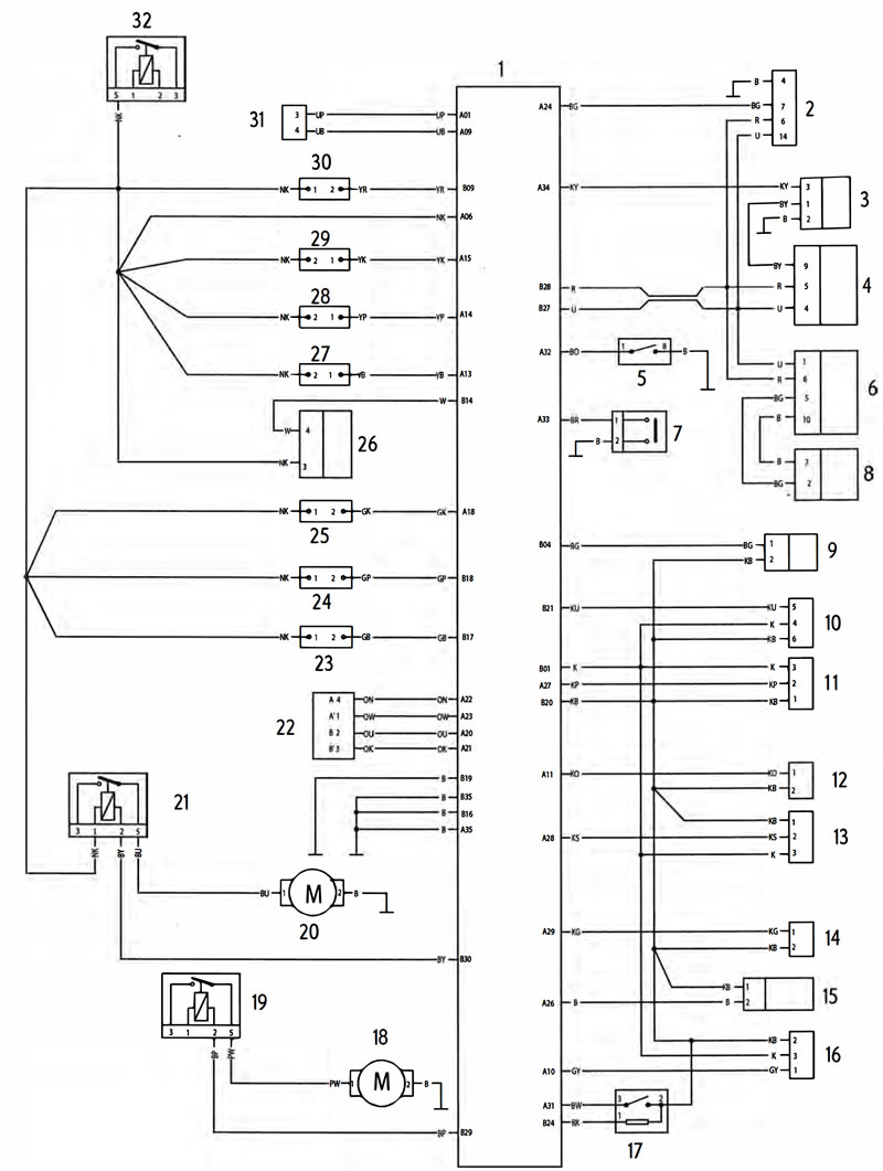
Key To Wiring Circuit Diagram
| Key | Item Description |
| 1 | Engine Control Module |
| 2 | Diagnostic Connector |
| 3 | Road Speed Sensor |
| 4 | Instrument Assembly |
| 5 | Clutch Switch |
| 6 | Immobiliser |
| 7 | Sidestand Switch |
| 8 | Ignition Switch |
| 9 | Fuel Level Sensor |
| 10 | Fall Detection Switch |
| 11 | Barometric Pressure Sensor |
| 12 | Intake Air Temperature Sensor |
| 13 | MAP Sensor |
| 14 | Coolant Temperature Sensor |
| 15 | Oxygen (Lambda) Sensor |
| 16 | Throttle Position Sensor |
| 17 | Gear Position Sensor |
| 18 | Fuel Pump |
| 19 | Fuel Pump Relay |
| 20 | Cooling Fan |
| 21 | Cooling Fan Relay |
| 22 | Idle Speed Control Stepper Motor |
| 23 | Coil 3 |
| 24 | Coil 2 |
| 25 | Coil 1 |
| 26 | Oxygen (Lambda) Sensor Heater |
| 27 | Fuel Injector 3 |
| 28 | Fuel Injector 2 |
| 29 | Fuel Injector 1 |
| 30 | Purge Valve |
| 31 | Crankshaft Position Sensor |
| 32 | Engine Control Module Relay |
Key To Wiring Colour Codes
| Code | Wiring Colour |
| B | Black |
| U | Blue |
| N | Brown |
| G | Green |
| S | Slate/Grey |
| О | Orange |
| K | Pink |
| R | Red |
| P | Purple |
| W | White |
| V | Yellow |
| LG | Light Green |
| LU | Light Blue |
Engine Management Circuit Diagram - Tiger 800 and Tiger 800XC