
Open circuit
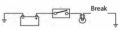
A break in an electrical circuit - current cannot flow. Usually caused by a break in a wire or cable or by a loose connection. Open circuits can often by intermittent, making diagnosis difficult.
Short circuit
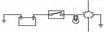
A 'short cut' in an electrical circuit - current by-passes the intended circuit, either to earth or to another, different circuit. Often caused by failure of the cable insulation due to chafing or trapping of the wire. There are two different types of short circuit - short to ground and short to Vbatt.
A short to ground means that the current is going to earth before it reaches the component it is supposed to feed. These are often caused by chafing of the harness to the frame or wires trapped between a bolted component, and will often blow the fuse on that circuit.
A short to Vbatt is a short to battery voltage (12 Volts) and is caused by a live power supply wire contacting an adjacent cable. Note that it is also possible for a 5 Volt sensor reference voltage to short to an adjacent circuit, which can also cause electrical failures and DTCs Diagnostic Trouble Code) to be stored.
When tracing a wire that is suspect, carefully check the circuit diagram before starting. Remember:
- a wire may diverge at a splice and go off to feed other circuits. If these circuits are working, check for wiring faults from the splice onwards.
- the circuit diagram is not an accurate guide to the actual location of the parts when fitted on the bike. lt is a schematic diagram of the circuits.
- particularly where engine management items are concerned, the circuit is only completed by the ECM. If the ECM is not connected, the circuit may register as open.
To Check Continuity:
Caution: Ensure the circuit being tested is switched off before measuring continuity. Damage to the Digital Multi Meter (DMM) may result from testing a 'live' circuit with the meter set to resistance (Ω). In the example below, the ground circuit continuity is being tested from the battery to the frame.
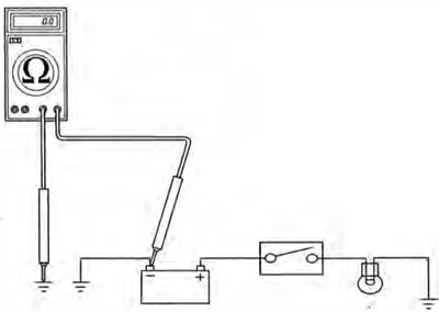
Continuity (Resistance) Check
- Locate each end of the wire.
- Set the Digital Multi Meter (DMM) to resistance check (Ω).
- Probe each end of the wire.
- If there is continuity, the meter will usually bleep or register the resistance of the cable.
- A high resistance figure could indicate a dirty or corroded connection.
- If there is a break in the wire, the meter will not bleep or register a resistance.
- By probing the wire in various places, the position of a high resistance or break in the wire (open circuit) can be narrowed down until it is found.
To Measure Voltage:
In the example below, the circuit voltage is being measured at the bulb positive (+) terminal.
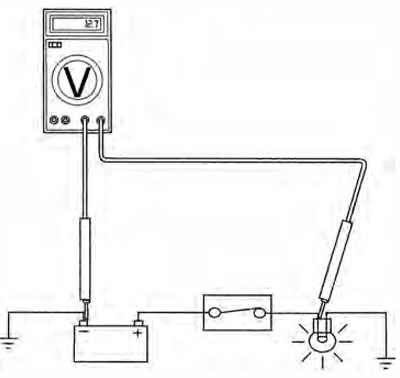
Voltage Check
- Turn the circuit to be tested 'ON'
- Set the Digital Multi Meter (DMM to Voltage check N). Ensure the multi meter is set to de volts for direct current circuits (most circuits) or ac volts for alternating current circuits (typically alternator output voltage tests).
- Set the range of the DMM to the range best suited to the voltage of the circuit being tested (typically 20 volts for most DMM). Refer to the DMM manufacturers instructions.
- Connect the black (ground) lead of the DMM to a reliable ground connection (usually the battery or frame ground).
- Locate the positive terminal of the wire or component to be tested.
- Connect the red (positive) lead of the DMM to the positive terminal.
- Read the voltage from meter.
Splices
Splices are probably the most common cause of wiring faults after connectors. Splices are made where two or more wires come together and diverge in different directions, usually to feed a different circuit.
To locate a splice, it is necessary to peel back the insulation and examine the splice for its integrity. The most common fault is where one of the wires at the joint has come adrift usually causing the circuit it feeds or earths to become 'dead'.
Switches
To check a switch, set the multimeter to resistance/continuity and probe the two pins that form a closed circuit when the switch is pushed. If the switch is working correctly, the resistance should register or the meter will bleep.
Relays
All relay cases have a circuit path engraved on them showing the circuit path across the electromagnet and the switch. Before making any checks, first note the pin designations, current paths, and whether or not there is a diode in either circuit path.
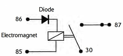
Make continuity checks across the electromagnet first, usually from pin, 86 (positive) to pin 85 (negative). If a diode appears in the circuit use the diode check on the multimeter (volts scale) in the direction of current flow. If there is no diode, use the resistance check facility. An open circuit or unusually high resistance value indicates a faulty relay.
To check the switch side, apply a 12 volt supply between pins 86 and 85. With the supply connected the relay should be heard to click and there should be continuity between pins 30 and 8Z An open circuit indicates a faulty relay.