
Connector
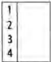
This illustration is used to show all multi-plug type electrical connectors on Triumph circuit diagrams. The numbers in the box relate to the terminal numbers of the connector pins. On ECMs with two connectors, the number would be prefixed with the letters 'A' or 'B' to identify each connector. An additional number outside the box will identify the component.
Diode
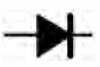
An electrical one-way valve. Diodes allow current to flow in one direction but will not allow it to return. The arrow, which forms part of the diode symbol, indicates the direction of current flow.
Electromagnetic Winding (solenoid)
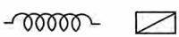
An electromagnetic winding (or solenoid) is used to convert an electrical current into a lateral movement. This can then be used to operate switches (as used in relays) or other components such as fuel injectors or secondary air injection solenoids.
Fuse
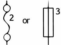
A fuse is a device which protects a circuit in the event of a fault. The fuse will 'blow' should a short circuit occur, protecting that circuit from further damage. The number next to the fuse on the circuit diagram indicates the position of the fuse in the fusebox.
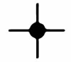
Ground or Earth Point
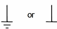
This symbol is used to show ground points. This is the negative connection to either the frame or engine, and is a common cause of intermittent faults due to loose or corroded connections.
Lamp or Bulb
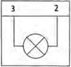
This symbol is used to show all types of light bulbs. The numbers in the box relate to the terminal numbers of the connector pins. An additional number outside the box will identify the component.
LED (Light Emitting Diode)
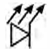
Triumph use LEDs for the alarm warning light, instrument illumination and warning lights, gear change lights and rear light/brake lights on various models.
Motor
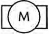
An electric motor. This could be the starter motor or a motor within an actuator, for example within the ABS modulator.
Relay
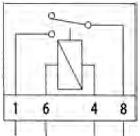
A relay is effectively an electromagnetic switch. To close the relay contacts and complete the circuit, an electromagnet in the relay is energised which causes the relay contacts to close, making the circuit complete.
Relays are used when the electrical current is too great for a mechanical switch, usually when the switching must be done quickly to prevent arcing across the switch contacts. If a mechanical switch were used, the mechanical switch contacts would quickly burn away.
Resistor
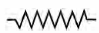
A device placed in a cable to reduce a voltage or restrict the maximum current a device can draw.
Splice
A hard cable joint where two or more cables are joined in the wiring harness. A potential source of both open and short circuits.
Switches
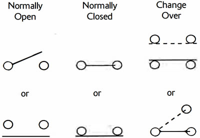
A mechanical device for completing or breaking a circuit. There are three common types of switch: Normally open, normally closed and change-over.