
Removal
| PART NUMBER | TOOL NAME |
| HD-48287 | TRIPLE TREE WEDGE TOOL |
1. Remove front brake calipers. See 2.10 FRONT BRAKE CALIPER: XR 1200X.
2. Remove front wheel assembly. See 2.5 WHEELS.
3. Remove front fender and bracket assembly. See 2.31 FRONT FENDER.
4. See Figure 2-145. Remove upper and lower fork bracket pinch bolts.
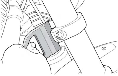
Figure 2-145. Insert triple tree wedge (typical)
5. Using TRIPLE TREE WEDGE TOOL (Part No. HD-48287), insert wedge in fork brackets to relieve clamping pressure on fork tubes.
6. Remove fork from upper and lower fork brackets.
7. Repeat steps for other side.
Disassembly
| PART NUMBER | TOOL NAME |
| HD-41177 | FORK HOLDING TOOL |
| HD-50083 | ROD CASE GUIDE SOCKET |
| HD-50084 | FORK CAP WRENCH |
Initial disassembly
Warning! Wear safety glasses or goggles when servicing fork assembly. Do not remove slider tube caps without relieving spring preload or caps and springs can fly out, which could result in death or serious injury.
Note. Count and record the number of rotations out (counterclockwise) for the preload adjuster.
1. See Figure 2-146. Back the preload off the fork spring.
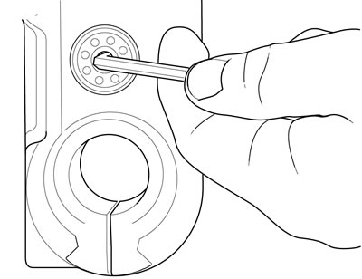
Figure 2-146. Preload adjuster
2. Clamp the outer tube in the FORK HOLDING TOOL (Part No. HD-41177).
3. See Figure 2-147. Loosen the fork cap with the FORK CAP WRENCH (Part No. HD-50084).
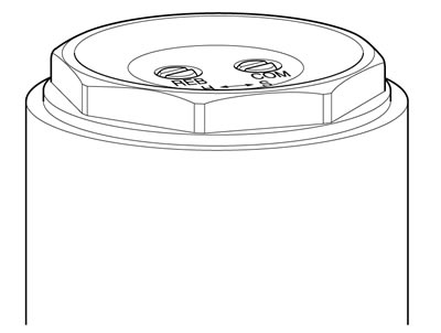
Figure 2-147. Loosen fork cap
4. See Figure 2-148. Pull the cap and piston rod up out of the outer tube and loosen the rod case guide with the ROD CASE GUIDE SOCKET (Part No. HD-50083).
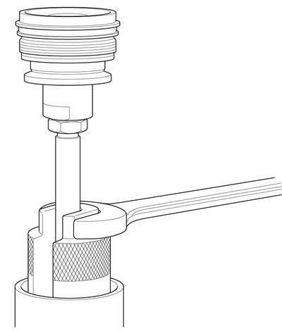
Figure 2-148. Rod guide nut socket
Note. Hold the rod case guide. Turn the axle clamp casting to unthread the case guide from the inner tube.
5. See Figure 2-149. Remove the piston rod assembly from the inner tube.
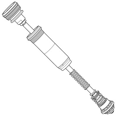
Figure 2-149. Piston rod assembly with rod case guide
Drain the fork oil
1. See Figure 2-150. Drain the oil into a pan. Remove:
- a. The upper spring collar
- b. The spring
- c. The lower spring collar
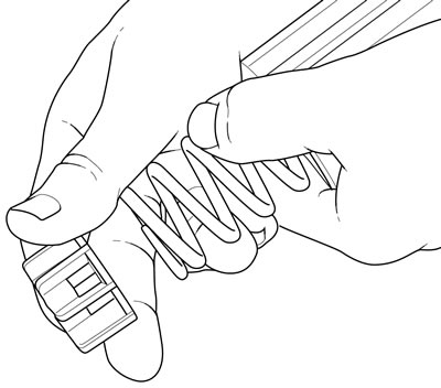
Figure 2-150. Remove the upper spring collar and the spring
2. Pump the inner tube 10 or more times to empty the oil from the fork.
Note. Dispose of fork oil in accordance with local regulations.
Complete disassembly
1. See Figure 2-151. Remove the stopper ring (18) from the groove inside the outer tube (13).
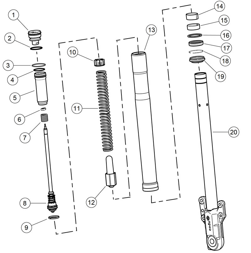
Figure 2-151. Fork assembly: XR 1200X: 1. Fork tube cap; 2. O-ring; 3. Slider ring; 4. O-ring; 5. Rod guide case; 6. Hex nut; 7. Preload spring; 8. Rod piston assembly; 9. Piston ring; 10. Upper spring collar; 11. Spring; 12. Lower spring collar; 13. Outer tube; 14. Slider bushing; 15. Guide bushing; 16. Seal spacer; 17. Oil seal; 18. Stopper ring; 19. Dust seal; 20. Inner tube
2. Slide the inner tube (20) out of the outer tube.
3. From the inner tube remove:
- a. Slide bushing (14)
- b. Guide bushing (15)
- c. Seal spacer (16)
- d. Oil seal (17)
- e. The stopper ring
- f. The dust seal (19)
Cleaning and inspection
1. Thoroughly clean components.
2. Replace all oil seals and O-rings.
3. Inspect components. Replace as necessary.
- a. Fork tube bushing and slider guide bushing for wear.
- b. Dust cover (where it rubs on fork tube) for wear.
- c. Springs for damaged coils.
- d. Fork tube or slider for bends or wear.
Assembly
| PART NUMBER | TOOL NAME |
| B-42571 | FORK SEAL DRIVER AND DUST BOOT INSTALLER |
| B-59000B | OIL LEVEL GAUGE |
| HD-41177 | FORK HOLDING TOOL |
| HD-50083 | ROD CASE GUIDE SOCKET |
| HD-50084 | FORK CAP WRENCH |
| FASTENER | TORQUE VALUE | |
| Fork piston rod hex nut: XR 1200X | 19-22 ft·lbs | 26-30 Nm |
| Rod guide case to inner tube: XR 1200X | 66 ft·lbs | 90 Nm |
| Fork cap to outer tube: XR 1200X | 21-29 ft·lbs | 29-39 Nm |
Piston rod service
1. Separate the hex nut from the fork cap and remove the fork cap and hex nut from the piston rod assembly.
Notes:
- The piston rod assembly should not be disassembled any further than is described.
- Do not use TYPE "E" HYDRAULIC FORK OIL to lubricate the components for assembly. Use BIG PISTON FORK OIL.
2. See Figure 2-152. Replace the O-ring on the fork cap.
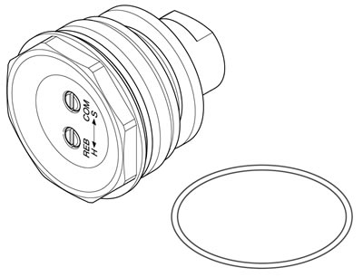
Figure 2-152. Fork cap and O-ring
3. See Figure 2-153. Replace the rod guide case O-ring (1) and the slider ring (2).
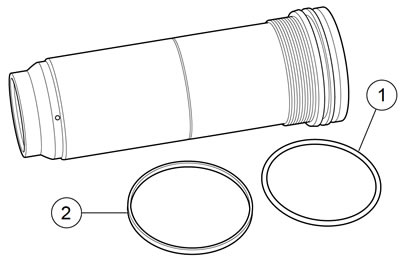
Figure 2-153. Rod guide case and O-rings: 1. Rubber O-ring; 2. Slider ring
4. Replace the rebound spring.
5. See Figure 2-154. Replace the fork piston ring.
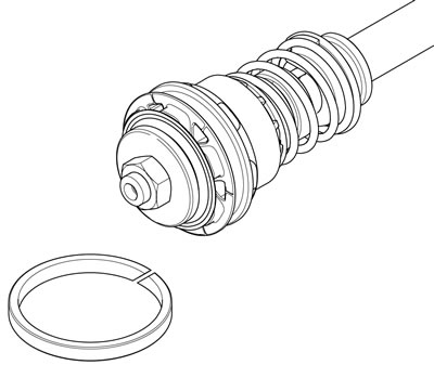
Figure 2-154. Fork rod piston and ring
6. Install the hex nut and the fork cap on the piston rod assembly.
7. Tighten to 19-22 ft·lbs (26-30 Nm).
Initial assembly
1. See Figure 2-155. Install on the inner fork tube:
- a. Dust seal (1)
- b. Oil seal stopper ring (2)
- c. Seal with the stamp side down (3)
- d. Seal spacer with the chamfer up (4)
- e. Guide bushing (6)
- f. Slide bushing (5)
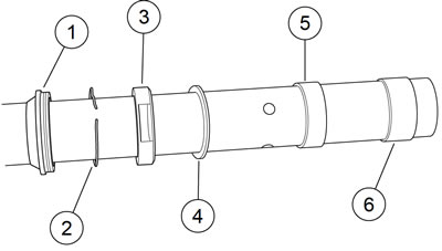
Figure 2-155. Inner tube components: 1. Dust seal; 2. Stopper ring; 3. Oil seal; 4. Spacer ring; 5. Slide bushing; 6. Guide bushing
Note. Do not use TYPE "E" HYDRAULIC FORK OIL to lubricate the components for assembly. Use BIG PISTON FORK OIL to lubricate the components for assembly.
2. Spread fork oil or sealing grease inside the lip of the oil seal.
3. Slide the inner tube into the outer tube.
4. See Figure 2-156. Seat the oil seal with the FORK SEAL DRIVER AND DUST BOOT INSTALLER (Part No. B-42571).
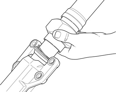
Figure 2-156. Seating the oil seal
5. Snap the stopper ring into the groove in the outer tube.
6. Seat the dust seal with the seal driver.
Fill with fork oil
1. Mount the fork assembly in the FORK HOLDING TOOL (Part No. HD-41177) and fully compress the inner tube.
Note. Measure the fork spring. Replace as necessary. Refer to Table 2-22.
2. Install:
- a. Lower spring collar
- b. Fork spring
- c. Upper spring collar
Note. Do not use TYPE "E" HYDRAULIC FORK OIL in the XR 1200X forks.
3. Fill fork with BIG PISTON FORK OIL until the oil reaches the side hole in the inner tube.
4. Pump the outer tube 8-10 times to expel the air from the assembly.
Note. Do not damage the slide ring on the rod guide case.
5. Install the piston assembly:
- a. Guide the piston rod into the inner tube.
- b. Hand tighten the rod guide case to the inner tube.
- c. Gently pull up on the outer tube to fit the slider ring to the outer tube.
6. Using the ROD CASE GUIDE SOCKET (Part No. HD-50083), tighten to 66 ft·lbs (90 Nm).
7. Fill fork with addition BIG PISTON FORK OIL until the oil spills over the rod guide case.
8. Pump the piston assembly/outer tube several times to expel any additional air.

Figure 2-157. Drawing off excess fork oil
9. See Figure 2-157. Use the OIL LEVEL GAUGE (Part No. B-59000B) to set the level of the oil in the outer fork tube to specification. Refer to Table 2-24.
Table 2-22. Minimum spring service length
| MODEL | in | mm |
| XR 1200X | 13.65 | 346.6 |
Table 2-23. Fork oil volume
| MODEL | oz | cm³ |
| XR 1200X | 19.6 | 580 |
Table 2-24. Fork oil level
| MODEL | in | mm |
| XR 1200X | 1.77 | 45 |
Complete assembly
1. Use the FORK CAP WRENCH (Part No. HD-50084) to install the fork cap and tighten to 21-29 ft·lbs (29-39 Nm).
2. Adjust the preload to identical settings on both forks.
Installation
| PART NUMBER | TOOL NAME |
| HD-48287 | TRIPLE TREE WEDGE TOOL |
| FASTENER | TORQUE VALUE | |
| Fork, front, bracket pinch screw | 30-35 ft·lbs | 40.7-47.5 Nm |
Notes:
- Fork tube installation height must match the opposite side exactly for proper vehicle operation, reliability and performance.
- When installing fork leg in fork brackets, do not twist fork leg to avoid damage to cosmetic finishes.
1. Identify left and right side fork assemblies.
2. Insert fork assembly from the lower fork bracket upward through the upper fork bracket.
3. Remove TRIPLE TREE WEDGE TOOL (Part No. HD-48287) used during removal process.

Figure 2-158. Fork installation height measurement
4. See Figure 2-158. Measure fork tube installation height. Adjust fork tubes to specification. Refer to Table 2-25.
Table 2-25. Fork installation height specifications
| MODEL | in | mm |
| XR 1200X | 0.388-0.468 | 9.86-11.88 |
5. Tighten pinch bolts to 30-35 ft·lbs (40.7-47.5 Nm).
6. Install front fender and bracket. See 2.31 FRONT FENDER.
7. Install front brake caliper hydraulic lines and install front brake calipers. See 2.10 FRONT BRAKE CALIPER: XR 1200X.
8. Install front wheel and align the wheel to the forks. See 2.5 WHEELS.