
Warning: Refer to the precautions given in Section 1 before starting work.
Removal
1. Remove the fuel tank (see Section 2).
2. Remove the air filter/duct housing, according to model (see Section 4). On XL models, also remove the rear cylinder ignition HT coil (see Chapter 5).
3. Undo the two screws securing the throttle cable holder to the carburettors and detach the cable ends from the carburettors, noting which fits where (see illustration).
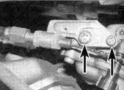
7.3. Undo the screws (arrowed) and detach the bracket from the carburettors
4. Undo the nut securing the choke plunger in each carburettor and draw the plungers out (see illustrations).

7.4a. Unscrew the nut (arrowed)...

7.4b ...and withdraw the choke plunger
5. Detach the air vent hoses from their unions, noting what fits where (see illustrations).

7.5a. Detach the vent hoses (arrowed) - XL models

7.5b. Detach the air vent hose - XRV models
6. On XL600V-T to X (1997 to 1999) models, XL650V models, and XRV750-T models onwards (1996-on), disconnect the throttle position sensor wiring connector (see illustration). On UK XL650V models, disconnect each carburettor heater wiring connector (see illustration).

7.6a. Disconnect the throttle position sensor wiring connector

7.6b. Trace the wiring from the heater (arrow) and disconnect it at the connector
7. On XRV750-L to N (1990 to 1992) models, release the idle speed adjuster from its holder. On all XRV750 models, release the clamp and detach the fuel supply hose from its union (see illustration). Also detach the overflow/drain hoses (see illustration).

7.7a. Disconnect the fuel hose...

7.7b ...and the overflow/drain hoses
8. Slacken the clamps securing the carburettors to the cylinder head inlet rubbers, then ease the carburettors off. noting how they fit, and manoeuvre them out of the frame as shown (see illustrations).

7.8a. Slacken the clamp screw (arrowed) on each side...

7.8b ...then lift the carburettors out of the intakes...

7.8c ...and remove them as shown
Note: Keep the carburettors as upright as possible to prevent fuel spillage from the float chambers and the possibility of the piston diaphragms being damaged.
9. Place a suitable container below the float chambers, then slacken the drain screws and drain all the fuel from the carburettors (see illustrations). Once all the fuel has been drained, tighten the drain screws securely.

7.9a. Carburettor drain screw (arrowed) - XL models

7.9b. Carburettor drain screw (arrowed) - XRV models
10. If necessary, release the clamps securing the inlet rubbers to the cylinder heads and remove them, noting how they fit.
Installation
11. Installation is the reverse of removal, noting the following.

7.11. Make sure the carburettors engage fully in the ducts
- Check for cracks or splits in the cylinder head inlet rubbers. If they have been removed from the cylinder head, make sure they are installed with the slotted tab on the adapter aligning with the raised lip on the underside ol the cylinder head stub .
- Make sure the carburettors are fully engaged with the cylinder head inlet rubbers and the clamps are securely tightened (see illustration).
- Make sure all hoses are correctly routed and connected and secured, and are not trapped or kinked.
- Check the operation of the choke ano throttle cables and adjust them as necessary (see Chapter 1).
- Check idle speed and carburettor synchronisation: adjust as necessary (see Chapter 1).