
Warning: Refer to the precautions given in Section 1 before proceeding.
Note: When reassembling the carburettors, be sure to use the new О-rings. seals and other parts supplied in the rebuild kit. Do not overtighten the carburettor jets and screws as they are easily damaged.
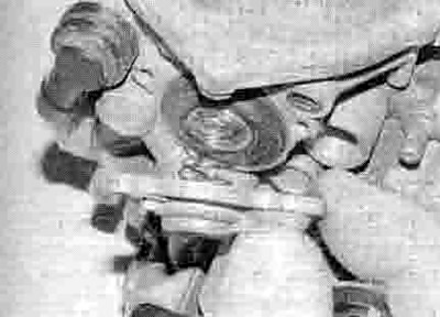
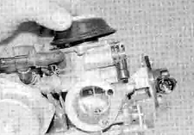
1. On XL models and XRV750-L to N (1990 to1992) models, fit a new air cut-off valve О-ring, making sure its flat side faces against the carburettor (see illustration and 8.1a). Fit the air cut-off valve diaphragm, making sure the pointed centre fits into the passage and it is properly seated (see illustration). Fit the spring between the cover and the diaphragm (see illustration), then locate the cover and tighten its screws securely, not forgetting the hose union retainer plate where fitted (see illustration 8.12a).

10.1a. Fit the О-ring, making sure the flat side is on the inside

10.1b. Locate the diaphragm...
10.1c ...then fit the spring and cover
2. On XRV750-P models onwards (1993-on), fit the air jet and air cut-off valve, using new О-rings, and secure the assembly with its screws (see illustration 8.1b). Connect the hose onto the union on the air cut-off valve.
3. Install the pilot screw (if removed) along with its spring, washer and О-ring, turning it in until it seats lightly (see illustration 5.1a or b). Now turn the screw out the number of turns previously recorded, or as specified at the beginning of the Chapter.
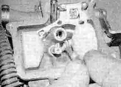
4. On XL models and XRV750-L to N (1990 to1992) models, install the float needle valve seat with its washer, making sure the filter is attached (see illustration).

10.4. Fit the needle valve seat with its washer
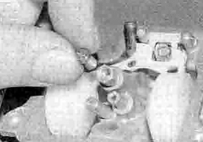
5. Hook the float needle valve onto the float tab (see illustration). Position the float assembly in the carburettor and install the pin. making sure it is secure (see illustrations 8.10b and a).

10.5. Hook the valve onto its tab
6. Screw the pilot jet into the body of the carburettor (see illustration).
10.6. Install the pilot jet...
7. Screw the needle jet into the body of the carburettor (see illustration). Screw the mam jet into the end of the needle jet (see illustration).

10.7a ...the needle jet...
10.7b ...and the main jet
8. To check the float height, hold the carburettor so the float hangs down, then tilt it back until the needle valve is just seated, but not so far that the needle's spring-loaded tip is compressed. Measure the distance between the base of the carburettor body and the bottom of the float with an accurate ruler (see illustration). The correct setting should be as given in the Specifications at the beginning of the Chapter. If the float height is incorrect, on brass floats it can be adjusted by carefully bending the float tab a little at a time until the correct height is obtained (see illustration 10.5); on plastic floats an incorrect float height can only be corrected by renewing the float.

10.8. Measuring the float height
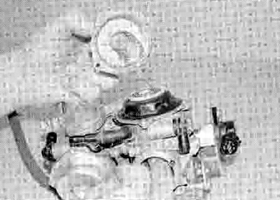
9. With the float height checked, fit a new seal into the groove in the float chamber, then fit the chamber onto the carburettor and secure it with the screws (see illustration).
10.9. Fit a new О-ring into the groove and install the float chamber
10. On XL models and XRV750-L to N (1990 to1992) models, carefully fit the jet needle into the piston (see illustration 8.4d). Check that the spring is fitted to the retainer and is secure (see illustration 8.4c). Insert the retainer and push down on the spring using a Phillips screwdriver or suitable socket and rotate it until its tabs lock under the protrusions in the piston (see illustration and 8.4a).

10.10. Insert the retainer, locating the spring on the top of the needle, then press down and turn to secure its tabs
11. On XRV750-P models onwards (1993-on), fit the washer underneath the jet needle head. Fit the needle into the piston, making sure the washer does not fall off. Fit a new О-ring into the groove in the needle holder and smear it with oil. Check that the spring is in the base of the needle holder, or install it if removed. Align the tabs on the holder with the slots in the piston and insert the holder, pushing it down until the О-ring is felt to locate in its groove. Remove the screw used on removal from the holder, if not already done.
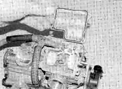
12. Turn the diaphragm inside out so that its rim faces down. Insert the piston/diaphragm assembly into the carburettor, ensuring the needle is correctly aligned with the needle jet (see illustration). Keep a finger on the bottom of the piston to keep it raised (inserting your finger via the air intake) so the diaphragm stays inside out - this will prevent the rim popping out of the groove. Align the loop on the diaphragm rim with its groove in the carburettor body, then press the diaphragm outer edge into its groove, making sure It is correctly seated (see illustration).
10.12a. Fit the piston into the carburettor...
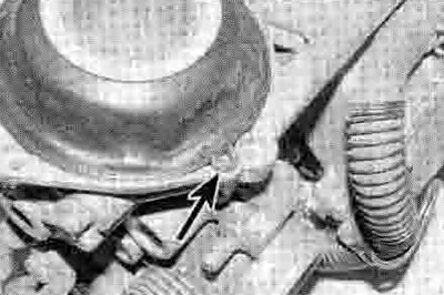
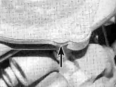
10.12b ...then press the diaphragm rim into the groove, making sure the loop (arrowed) locates correctly
13. Keeping the piston raised, fit the spring, locating it over the needle holder (see illustration). Fit the top cover onto the carburettor, locating the top of the spring inside the raised section in the cover (see illustration). Align the protrusion on the cover with the loop on the diaphragm (see illustration). Make sure the diaphragm rim stays seated in its groove and does not get pinched by the cover, then install the cover screws and tighten them securely. You can now let the piston drop. Check that the piston moves up and down smoothly.
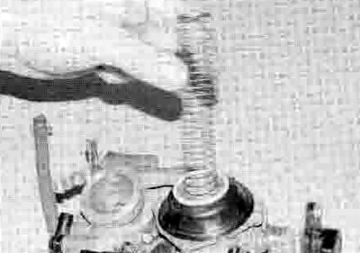
10.13a. Insert the spring...
10.13b ...then fit the cover...
10.13c ...making sure the protrusion (arrowed) aligns with the loop
14. On XRV750-P models onwards (1993-on), fit new air intake funnel О-rings into the groove in the intake side of each carburettor. Fit the air funnel Into the holder and rotate it so that its tabs are locked in place. Align the cutouts in the air funnel with the corresponding raised lands on the intake bore, and fit the pins on the holder into the holes in the carburettor body. Tighten the four screws securely.
15. If removed, install the throttle position sensor (See Chapter 5).
16. Install the carburettors (see Section 7).