
Warning: Refer to the precautions given in Section 1 before starting work.
Disassembly
1. Remove the carburettors (see Section 7).
Note: Do not separate the carburettors unless absolutely necessary: each carburettor can be dismantled sufficiently for all normal cleaning and adjustments while in place on the mounting brackets. Dismantle the carburettors separately to avoid interchanging parts (see illustrations).
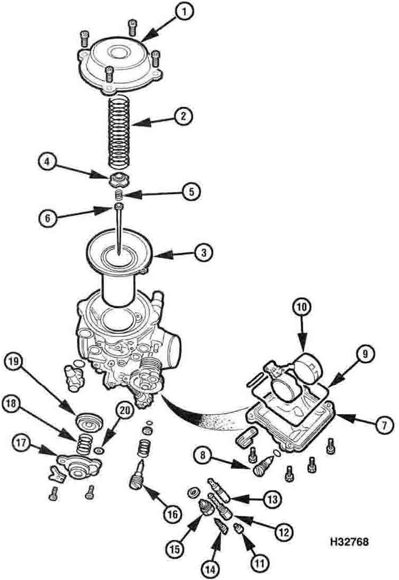
8.1a. Carburettor components - XL models and XRV750-L to N (1990 to 1992) models: 1. Top cover; 2. Spring; 3. Piston/diaphragm; 4. Needle holder; 5. Spring; 6. Jet needle; 7. Float chamber; 8. Drain screw; 9. Rubber seal; 10. Float and float pin; 11. Main jet; 12. Needle jet; 13. Pilot jet; 14. Float needle valve; 15. Float needle valve seat; 16. Pilot screw; 17. Air cut-off valve cover; 18. Spring; 19. Diaphragm; 20. O-ring
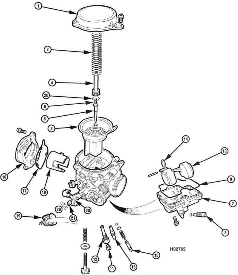
8.1b. Carburettor components - XRV750-P models onwards (1993-on): 1. Top cover; 2. Spring; 3. Piston/diaphragm; 4. Needle holder; 5. Spring; 6. Jet needle and washer; 7. Float chamber; 8. Drain screw; 9. Rubber seal; 10. Float and float pm; 11. Main jet; 12. Needle jet; 13. Pilot jet; 14. Float needle valve; 15. Pilot screw; 16. Air intake funnel holder; 17. O-ring; 18. Air intake funnel; 19. Air cut-off valve; 20. O-ring; 21. Air jet
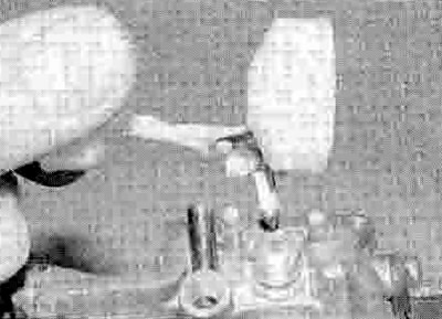
2. Unscrew and remove the top cover retaining screws (see illustration). Lift off the cover and remove the spring from inside the piston.
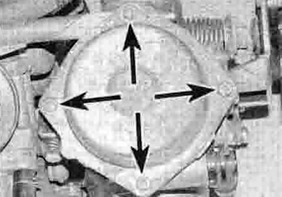
8.2. Undo the screws (arrowed) and remove the cover and spring
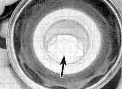
3. Carefully peel the diaphragm away from its sealing groove in the carburettor and withdraw the diaphragm and piston assembly.
Caution: Do not use a sharp instrument to displace the diaphragm as it is easily damaged. Note how the tab on the diaphragm fits in the recess in the carburettor body.
4. On XL models and XRV750-L to N (1990 to 1992) models, push down on the jet needle retainer using either a Phillips screwdriver or a suitable socket and rotate it until its tabs are released from the protrusions inside the piston (see illustration). Remove the retainer, noting the spring on its underside - it should stay in place, but take care not to lose it and remove it if it is loose (see illustrations). Push the needle up from the bottom of the piston and withdraw it from the top (see illustration).
8.4a. Turn the retainer (arrowed) to release its tabs...

8.4b ...then withdraw it...
8.4c ...noting its spring
8.4d. Remove the needle
5. On XRV750-P models onwards (1993-on) models, thread a 4 mm screw into the top of he needle holder (one of the top cover retaining screws is ideal), then grasp the screw head using a pair of pliers and carefully draw the holder out of the piston. Note the spring in the base of the needle holder - it should stay in place, but take care not to lose it and remove it if it is loose. Push the needle up from the bottom of the piston and withdraw it from the top. Note the washer that fits between the needle head and the piston. Check the condition of the О-ring on the holder and replace it with a new one if it is damaged, defonned or deteriorated.
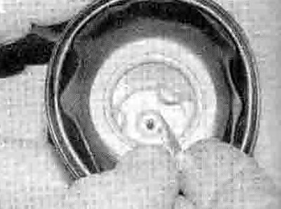
6. Undo the screws seeming the float chamber to the base of the carburettor and remove it (see illustration). Remove the rubber seal and discard it as a new one must be fitted.

8.6. Remove the screws (arrowed) and lift off the chamber
7. Unscrew and remove the main jet from the needle jet (see illustration).

8.7. Remove the main jet...
8. Unscrew and remove the needle jet (see illustration).
8.8 ...the needle jet...
9. Unscrew and remove the pilot jet (see illustration).

8.9 ...and the pilot jet (arrowed)
10. Using a pair of thin-nose pliers, carefully withdraw the float pivot pin (see illustration). If necessary, displace the pin using a small punch or a nail. Remove the float and unhook the float needle valve, noting how it fits onto the tab on the float (see illustration). On XL models and XRV750-L to N (1990 to 1992) models unscrew and remove the float needle valve seat, taking care not to damage its gauze filter (see illustration).
8.10a. Displace the float pivot pin...
8.10b ...and remove the float assembly
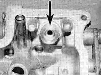
8.10c. Float needle valve seat (arrowed)
11. The pilot screw can be removed from the carburettor, but note that its setting will be disturbed (see Haynes Hint opposite). Unscrew and remove the pilot screw along with its spring, washer and О-ring (see illustration 5.1a or b).
To record the pilot screw's current setting, turn the screw in until it seats lightly, counting the number of
turns necessary to achieve this, then fully unscrew it. On installation, the screw is simply backed out the number of turns you've recorded.
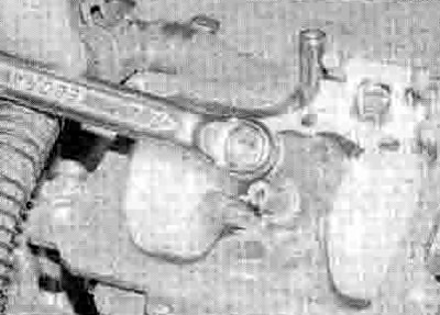
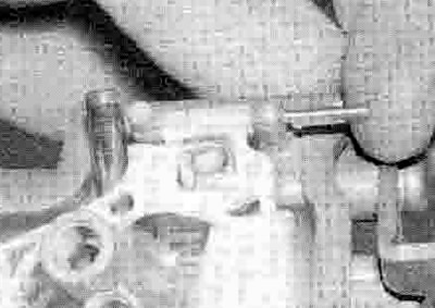
12. Ori XL models and XRV750-L to N (1990 101992) models, remove the two screws securing the air cut-off valve cover and its plate, noting that it is under spring pressure (see illustration). Carefully release the cover and remove the spring and cut-off valve diaphragm, noting how they fit (see Illustration). Also remove the O-ring.

8.12a. Undo the screws (arrowed)...
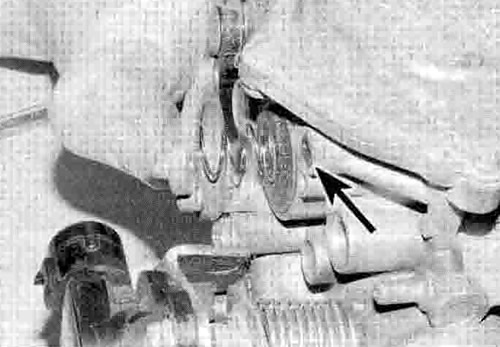
8.12b .. then release the cover and remove the spring and diaphragm. Also remove the О-ring (arrowed)
13. On XRV750-P models onwards (1993-on). detach the hose from the union on the air cutoffvalve, then remove the screw and draw the valve out of the carburettor. Remove the air jet. Discard the O-rings as new ones must be used.
14. On XL600V-T to X (1997 to 1999) models, XL650V models, and XRV750-T models onwards (1996-on), do not remove the throttle position sensor unnecessarily. If you do need to remove it, refer to Chapter 5.
15. On XRV750-P models onwards (1993-on), undo the screws securing the air intake funnel assembly and remove it, noting how it fits. Separate the funnel from its holder if required by twisting it to free the tabs, noting how it fits. Discard the О-ring if it is in any way damaged, deformed or deteriorated.
Cleaning
Caution: Use only a petroleum based solvent for carburettor cleaning. Don't use caustic cleaners.
16. Submerge the metal components in the solvent following the product manufacturer's instructions.
17. After the carburettor has soaked long enough for the cleaner to loosen and dissolve most of the varnish and other deposits, use a nylon-bristled brush to remove the stubborn deposits. Rinse it again, then dry it with compressed air.
18. Use a jet of compressed air to blow out all of the fuel and air passages in the main and upper body, not forgetting the air jets in the carburettor intake.
Caution: Never clean the jets or passages with a piece of wire ora drill bit, as they will be enlarged, causing the fuel and air metering rates to be upset.
Inspection
19. Inspect the choke plunger assembly for wear and damage (see illustration 7.4b).
20. If removed from the carburettor, check the tapered portion of the pilot screw and the spring and О-ring for wear or damage. Replace them with new ones if necessary.
21. Check the carburettor body, float chamber and top cover for cracks, distorted sealing surfaces and other damage. If any defects are found, replace the faulty component, although replacement of the entire carburettor will probably be necessary (check with a Honda dealer on the availability of separate components).
22. Check the piston diaphragm for splits, holes and general deterioration. Holding it up to a light will help to reveal problems of this nature.
23. Insert the piston in the carburettor body and check that it moves up-and-down smoothly. Check the surface of the piston for wear. If it's worn excessively or doesn't move smoothly in the guide, renew the components as necessary.
24. Check the jet needle for straightness by rolling it on a flat surface such as a piece of glass. Replace it with a new one if it's bent or if the tip is worn.
25. Check the tip of the float needle valve and the valve seat. If either has grooves or scratches in it, or is in any way worn, they should be renewed as a set. Gently push down on the rod on the top of the needle valve then release it - if it doesn't spring back, replace the valve with a new one.
26. Operate the throttle shaft to make sure the throttle butterfly valve opens and closes smoothly. If it doesn't, cleaning the throttle linkage may help. Otherwise, replace the carburettor with a new one.
27. Check the float for damage. This will usually be apparent by the presence of fuel inside the float. If the float is damaged, it must be replaced with a new one.
28. On XL models and XRV750-L to N (1990 to 1992) models, check the air cut-off valve diaphragm for splits, holes and general deterioration. Holding it up to a light will help to reveal problems of this nature. Also check the spring for deformation and weakness and replace it with a new one if necessary.
29. On XRV750-P models onwards (1993-on), to check the air cut-off valve, apply a vacuum to the union on the valve cover With the vacuum applied, air should not be able to flow between the ports in the valve. With no vacuum applied, air should be able to flow. If the valve does not behave as described, replace it with a new one.