
Warning: Refer to the precautions given in Section 1 before starting work.
Check
1. The fuel pump is controlled through a cutoff relay, so that it runs whenever the ignition is switched ON and the ignition is operative (i.e., only when the engine is turning over). As soon as the ignition is killed, the relay cuts off the fuel pump's electrical supply (so that there is no risk of fuel being sprayed out under pressure in the event of an accident).
2. The fuel pump is mounted below the rear of the fuel tank - remove the left-hand side panel to access it (see Chapter 8) (see illustration). On L to N (1990 to 1992) models the relay is mounted below the instrument cluster - remove the fairing to access it (see Chapter 8) (see illustration). On P models onwards (1993-on) the relay is mounted on the rear sub-frame on the left-hand side - remove the left-hand side panel to access it (see Chapter 8) (see illustration).
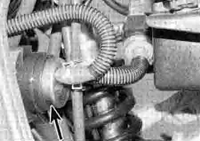
15.2a. Fuel Dump (arrowed)
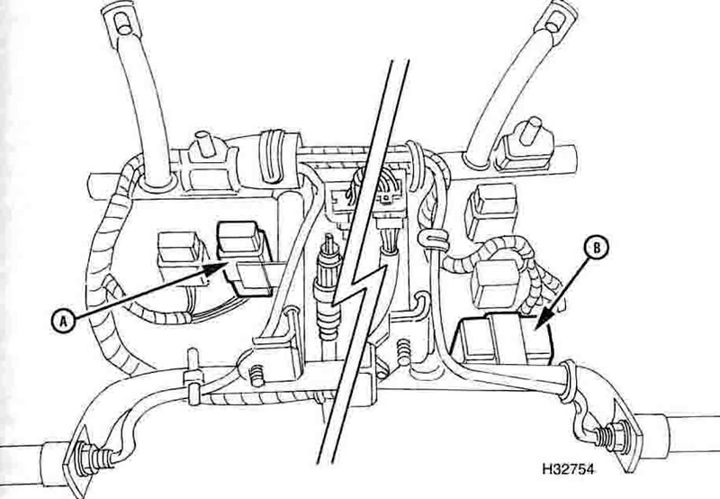
15.2b. Fuel cut-off relay (A), fuel warning light circuit checker (B) - XRV750-L to N·models

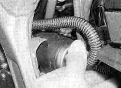
15.2c. Fuel cut-off relay (arrowed) - XRV750-P models onward
3. It should be possible to hear or feel the fuel pump running whenever the engine is turning over - either place your ear close beside the pump or feel it with your fingertips. If you can't hear or feel anything, check the circuit fuse (see Chapter 9). If the fuse is good, check the pump and relay for loose or corroded connections or physical damage and rectify as necessary. If all is good so far, perform the following checks:
4. Disconnect the relay wiring connector (see illustration 15.2c). Connect the positive (+) probe of a voltmeter to the blаск/red wire terminal on the loom side of the wiring connector and the negative (-) probe to earth. With the ignition switch ON there should be battery voltage present. If there is no voltage, check the blаск/red wire for faults, referring to the Wiring Diagrams at the end of Chapter 9.
5. If battery voltage was present, check for continuity in the black/blue wire between the relay connector and the pump connector, and then between the green wire in the pump connector and earth (ground). If there is no continuity there is a fault in the black/blue or green wire. If there is continuity, check for continuity in the blue/yellow or black/yellow wire (according to model) between the relay and the ignition control unit. If there is none, trace the fault and repair the wire. If all is good, short between the blаск/red and black/blue wire terminals in the relay wiring connector (thereby effectively by-passing it). Now check for battery voltage at the fuel pump wiring connector black/blue wire with the ignition ON. If there is voltage, the relay is faulty and must be replaced with a new one.
6. If the pump still does not work, trace the wiring from the pump and disconnect it at the 2-pin wiring connector - remove the seat and raise the rear of the fuel tank to access it (see Chapter 8 and Section 2). but be prepared to remove the fuel tank if access to the connector is too restricted with it in place. Using a fully charged 12 volt battery and two insulated jumper wires, connect the positive (+) terminal of the battery to the pump's black/blue terminal, and the negative (-) terminal of the battery to the pump's green terminal. The pump should operate. If the pump does not operate it must be replaced with a new one. If the pump works, check for battery voltage at the black/blue terminal on the supply side of the connector with the ignition ON. If there is no voltage, check the wiring.
7. If the pump operates but is thought to be delivering an insufficient amount of fuel, first check that all fuel hoses are in good condition and not pinched or trapped. Check that the in-line filter, the strainer in the fuel tank and the fuel delivery hoses are not blocked.
8. The fuel pump's output can be checked as follows: make sure the ignition switch is OFF. If it was removed, install the fuel tank in the raised position (see Section 2).
9. Release the clamp securing the fuel supply hose to the three-way union on the carburettors, being prepared to catch any residual fuel (see illustration 7.7a). Place the end into a graduated beaker suitable for holding about 1/4 litre of petrol.
10. Disconnect the relay wiring connector (see illustration 15.2c). Using a short length of insulated jumper wire, connect between the black/red and the black/blue wire terminals of the connector
11. Set the kill switch to RUN. then turn the ignition switch ON and let fuel flow from the pump into the beaker for 5 seconds, then switch the ignition OFF.
12. Measure the amount of fuel that has flowed into the beaker, then multiply that amount by 12 to determine the fuel pump flow rate per minute. The minimum flow rate required is 900 cc per minute. If the flow rate recorded is below this, then the fuel pump must be replaced with a new one.
Removal
13. Make sure the ignition is switched OFF.
14. The fuel pump is mounted below the rear of the fuel tank - remove the left-hand side panel to access it (see Chapter 8) (see illustration). Trace the wiring from the pump and disconnect it at the black 2-pin wiring connector - remove the seat and raise the rear of the fuel tank to access it (see Chapter 8 and Section 2), but be prepared to remove the fuel tank if access to the connector Is too restricted with it in place. Free the wiring from any clips or ties and feed it back to the pump, noting its routing. Make a note or sketch of which fuel hose fits on which union on the pump as an aid to installation. Using a rag to mop up any spilled fuel, disconnect the two hoses from the pump. Displace the pump from its mount and either disconnect the drain hose from the underside or remove the pump with it attached, noting its routing.
15.14. Draw the pump off its mounting lug and remove it
15. On L to N (1990 to 1992) models the relay is mounted below the instrument cluster - remove the fairing to access it (see Chapter 8) (see illustration 15.2b). On P models onwards (1993-on) the relay is mounted on the rear sub-frame on the left-hand side - remove the left-hand side panel to access it (see Chapter 8) (see illustration 15.2c). Disconnect the relay wiring connector and remove the relay from its mounting.
Installation
16. Installation is the reverse of removal. Make sure the fuel hoses are correctly and securely fitted to the pump - the hose from the in-line filter attaches to the union marked INLET; the hose to the carburettors attaches to the other union. Start the engine and check carefully that there are no leaks at the pipe connections.