
Attention! Determine the position of each part being removed. Organize parts by accessory (for example, inlet or outlet) so that they can be assembled in their original position.
Camshaft
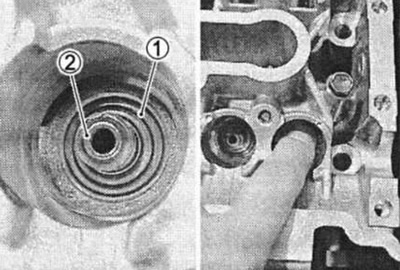
Both shafts should be checked for journal runout and also for cam and journal wear if abnormal noise or vibration or lack of power is noted when the engine is running. All this can be caused by wear on the cams or a change in the profile to an unacceptable level.
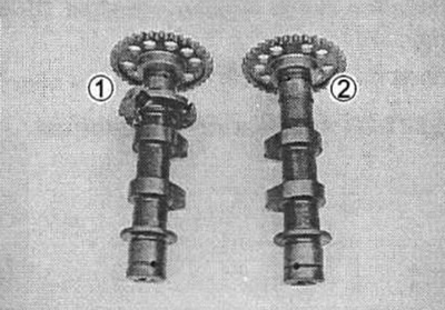
(1) Exhaust camshaft; (2) Intake camshaft
Automatic decompressor
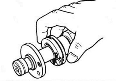
Check the mobility of the decompressor weight manually. If there is any jamming, replace it with a new one.
Attention! Do not attempt to disassemble the camshaft and decompressor. These units cannot be repaired.
Cam wear
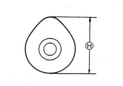
Cam wear often causes misalignment of the valve timing, which reduces engine power.
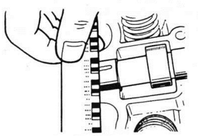
Measure the height of the cam with a micrometer. If the cams are worn beyond the acceptable limit, replace the camshaft with a new one.
09900-20202: Micrometer (25-50 mm).
Cam height limit (N):
- Intake valve: 35.02mm
- Exhaust valve: 34.92mm
Wear of camshaft cams
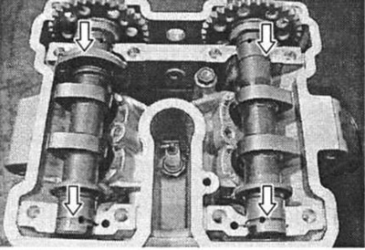
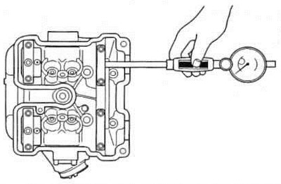
With the camshafts installed, measure the clearance using plastic gauges.
09900-22301: Plastic gauge
09900-22302: Plastic gauge
Gap in camshaft supports (inlet and outlet) permissible gap: 0.150 mm
Tighten the cover bolts evenly, crosswise, to the specified torque.
Bolt tightening torque: 10 Nm (1.0 kgf-m).
Note. Do not rotate the camshaft with a plastic gauge installed. Remove the covers and determine the width of the compressed plastic gauge using the scale. Measure at the widest part of the compressed plastic gauge. If the gap exceeds the permissible value, measure the inner diameter of the cap and the outer diameter of the neck. Replace the camshaft or cylinder head, whichever is causing the increased clearance.
09900-20602: Dial indicator (1/1000 mm)
09900-22403: Bore gauge for measuring small diameters
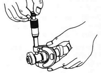
Cap inner diameter (INLET and EXHAUST). Normal: 22.012–22.025 mm
09900-20205: Micrometer (0–25 mm)
Neck diameter (INLET and EXHAUST). Normal: 21.959–21.980 mm
Neck beating
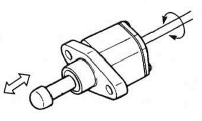
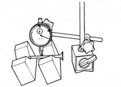
Place the shaft on the prisms and measure the runout using a dial indicator. If the runout exceeds the permissible limit, replace the camshaft with a new one.
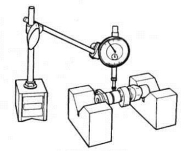
09900-20607: Dial indicator (1/100 mm)
09900-20701: Magnetic stand
09900-21304: Prisms (100 mm)
Neck runout: Maximum permissible runout: 0.10 mm
Timing chain tension regulator
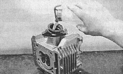
The timing chain tension is maintained by an automatically adjustable adjuster. Insert a slotted screwdriver into the slot of the adjuster and turn it clockwise, loosening the tension, remove the screwdriver to make sure there is forward movement of the tensioner rod. If the rod sticks or the spring mechanism does not work, replace the regulator assembly with a new one.
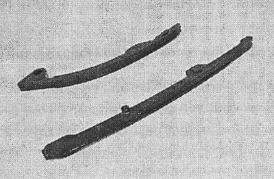
Timing chain guide and chain tensioner
Check the condition of the timing chain guide and tensioner for wear and damage. If damaged, replace them with new ones.
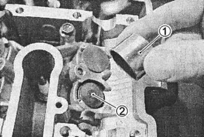
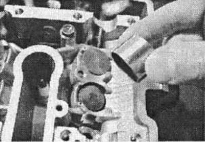
Cylinder head inspection
Remove pusher 1 and washers 2 manually or using a magnetic tool.
Using a special tool, compress the valve springs.
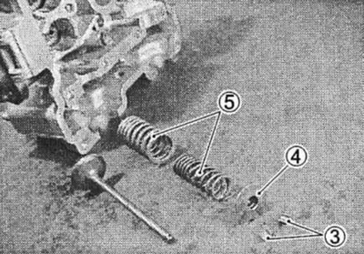
Remove the crackers (3) from the valve stem.
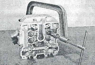
09916-14510: Valve puller
09916-14521: Puller accessory (spring compression bushing)
09916-84511: Tweezers
Remove the washers (4) valves and springs (5).
Remove the valve from the other side.
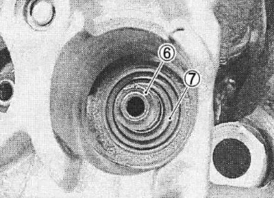
Valve stem seals (6) Narrow-nose pliers.
Remove the spring seat (7).
Cylinder head deformation
Clean the combustion chamber from carbon deposits.
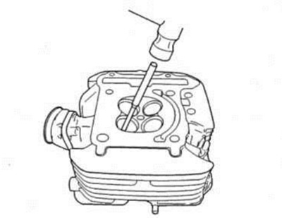
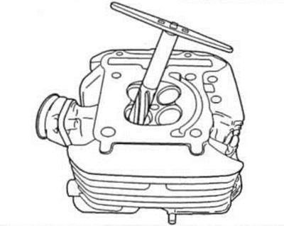
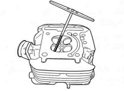
Check the head mating surface for flatness using a straight edge and feeler gauge. Take measurements in several places. If in any place the gap exceeds the permissible limit, replace the head with a new one.
09900-20803: Dipstick
Tolerance limit for non-flatness: 0.05 mm
Allowable runout: 0.05 mm
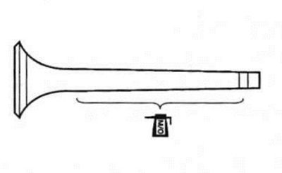
Valve chamfer wear
Visually check the condition of the valve chamfers for wear and damage. If any defects are found, replace the valve with a new one. Determine the width of the belt (T). If it is less than acceptable, replace the valve with a new one.
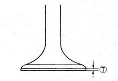
Belt width (T).
Acceptable limit: 0.5 mm
Allowable runout: 0.05 mm
Valve stem runout
Place the valve on the prisms and measure the runout using an indicator as shown in the figure. If the runout value exceeds the permissible value, replace the valve with a new one.
09900-20701: Magnetic stand
09900-20607: Dial indicator (1/100 mm)
09900-21304: Prisms (100 mm)
09900-20701: Magnetic stand
Allowable runout: 0.05 mm
Valve head radial runout
Place the valve on the prisms and measure the radial runout of the head using an indicator, as shown in the figure. If the runout value exceeds the permissible value, replace the valve with a new one.
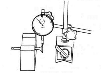
09900-20607: Dial indicator (1/100 mm)
09900-20701: Magnetic stand
09900-21304: Prism (100 mm)
Head runout tolerance: 0.03mm
Valve stem play
Raise the valve approximately 10 mm above the seat. Measure the play along the rod in two mutually perpendicular directions "X" and "Y". Position the indicator as shown in the figure. If the play exceeds the permissible value, determine what needs to be replaced - the valve or the guide sleeve.
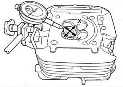
09900-20607: Indicator (1/100 mm)
09900-20701: Magnetic stand
Maximum permissible play: 0.35 mm
Valve stem wear
Measure the diameter of the valve stem with a micrometer. If the diameter exceeds the permissible limits, replace the valve with a new one. If the diameter of the rod is within tolerance and the play exceeds the permissible limit, replace the guide bushing. After replacement, check the play.
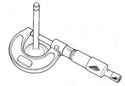
09900-20205: Micrometer (0-25 mm)
Rod diameter tolerance:
- Intake valve: 4.475–4.490 mm
- Exhaust valve: 4.455–4.470 mm
Valve sleeve inspection
Press out the bushing using a special tool.
09916-43210: Bushing removal/installation tool
Note.
- Do not reuse removed bushings.
- As a replacement, use only bushings with repair dimensions along the outer diameter.
- Unscrew the hole in the cylinder head for the bushing using a special reamer with a handle.
09916-34580: Special reamer (10.8 mm)
09916-34542: Reamer handle
Lubricate the bushing with oil and press it into the head using a puller.
09916-43210: Guide bushing puller
09916-43220: Guide bushing puller part
Attention! Failure to lubricate the guide bushing before pressing it in may result in damage to the head or bushing.
After installing the guide bushings, unscrew their holes using special reamers. After unrolling, clean the holes.
09916-33210: Bushing reaming (4.5 mm)
09916-34542: Reamer handle
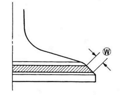
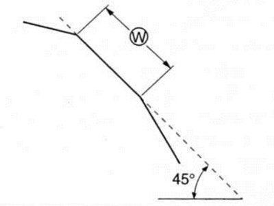
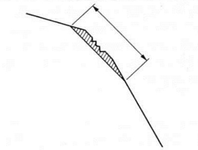
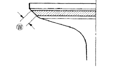
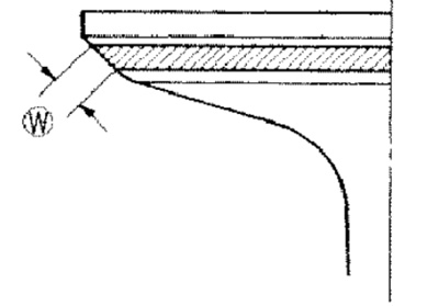
Valve seat width
Cover the valve seat evenly with Prussian glaze. Reinstall the valve. Press the valve to the special seat. device and turn it so that a clear imprint remains on the chamfer at the point of contact.
09916-10911: Valve lapping tool
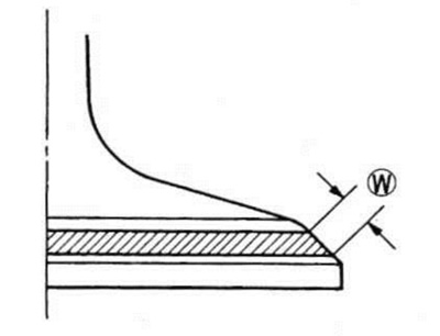
The ring mark on the valve chamfer should not have breaks. In addition, its width must correspond to the standard.
Landing belt width (W). Normal: 0.9–1.1 mm
If there are deviations in size, grind the chamfer.
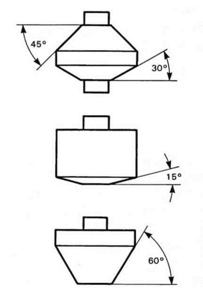
Valve seat maintenance
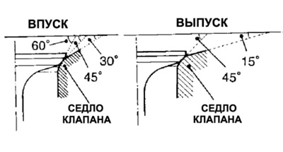
The intake and exhaust valve seats are machined at three different angles. Contact surfaces are machined at an angle of 45°.
| Inlet | Release | |
| 45° | N-122 | N-122 |
| 15° | — | N-121 |
| 30° | N-126 | — |
| 60° | N-111 | — |
For USA:
- Saddle Balls: N-111, N-121, N-122 and N-126
- Mandrel: N-100-4.5
For other countries:
- 09916-21111: Set of cutters (including N-111, N-121 and N-122)
- 09916-20630: Roller cutter for saddle N-126
- 09916-20640: Mandrel N-100 - 4.5
Note. Use the N-100-4.5 mandrel with a set of cutters N-111, N-121, N-122, and N-126.
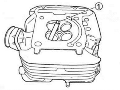
Attention! The contact surface of the seats must be checked after each treatment.
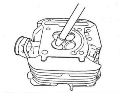
When installing the mandrel (1), turn it slightly.
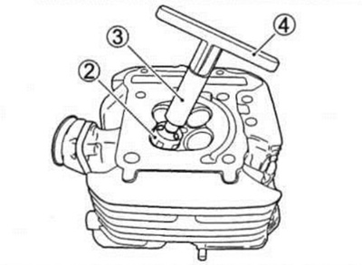
Install the mandrel firmly. Use a 45°cutter (2), mandrel (3) and a pen (4).
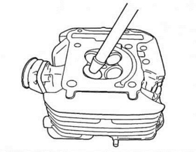
Seat pre-treatment
Remove carbon deposits and renew the surface using a 45°angle cutter. Make 1-2 turns.
Measure your saddle width every time (W).
If the saddle is covered with sores (pitting) or burnt, process the saddle deeper.
Note. Cut only the minimum necessary to prevent replacement of the shims used to adjust the cam clearance.
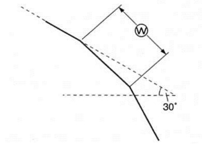
Treatment to narrow the saddle contact area
If the contact surface on the valve is too high or the collar is wider than acceptable, use a 30°cutter (for intake valve) and 15° (for graduation), to lower or narrow the contact surface
The contact surface is too high on the valve face or the collar is too wide
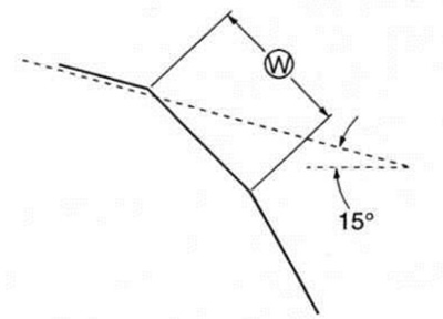
Finishing the saddle
If the contact surface is too low or too narrow, use a 60°cutter (for intake valve), to raise and widen the contact band. If the belt is too high or too wide, use a 15°cutter (for graduation) and 30° (for intake) valves to lower or narrow the contact belt.
Once the desired belt width and position have been achieved, lightly work the surface with a 45°roller cutter to remove any burrs left from the previous treatment.
The contact surface is too high on the valve face or the collar is too wide
Attention! Do not use lapping paste after finishing. The finished valve seat should have a velvety surface, but not polished or shiny. This will provide the necessary compliance for proper valve seating, which will occur within the first seconds of engine operation.
Note. After machining the valve seats, be sure to check the clearance in the valve mechanism after assembling the cylinder head (see 2-5).
Checking valve tightness
With the valves and springs installed, pour some gasoline into the intake or exhaust tract. Make sure gasoline does not pass through the valves. If a leak is detected, repair the sealing surface.
Warning! Gasoline is highly flammable and explosive. Keep it away from sparks, heat and flame.
Valve spring
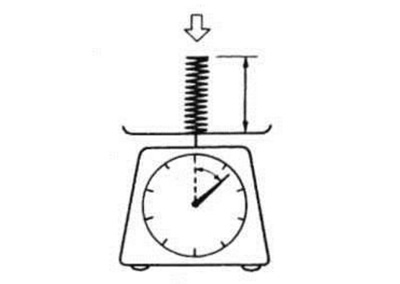
The spring force holds the valve tightly in place. Weak springs reduce engine power and cause a rattling sound from the valve train. Check the valve springs for proper force by measuring their free length and the force required to compress them. If the spring length is short or the spring force is out of tolerance, replace the inner and outer spring as a set.
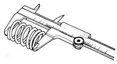 |  |
Tolerance on free length of valve springs (INLET and EXHAUST):
- For inner spring: 38.6mm
- For external spring: 40.6 mm.
Tolerance for spring compression force (INLET AND EXHAUST):
- For inner spring: 48–58 N (4.9–5.9 kgf) at a length of 29.9 mm
- For external spring: 133–153 N (13.6–15.6 kgf) at a length of 33.4 mm
Assembly
Install the spring seats (1).
Apply molybdenum grease to valve stem seals (2) and press them into place.
Warning! Do not reuse valve stem seals.
Apply molybdenum grease to the valves as shown in the picture, then insert them into the guide bushings.
Attention! When reinstalling the valves, be careful not to damage the seal lips.
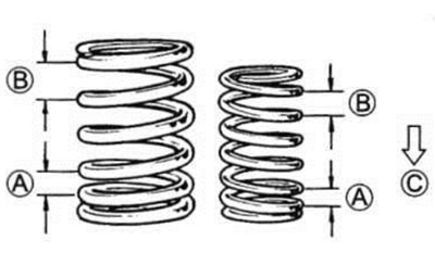
Install valve springs in smaller increments (A) towards the cylinder head. (IN) Bigger step. (WITH) Down.
 |  |
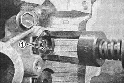
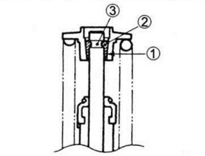
Install the valve washer by compressing the springs with a puller. Install the halves of the crackers and ease the load on the springs so that the crackers (1) got between the washer and the valve stem. Make sure the rounded protrusions (2) The crackers fit tightly into the groove at the end of the valve stem.
09916-14510: Valve puller
09916-14521: Puller accessory
09916-84511: Narrow-nose pliers
 |  |
Attention! Install the parts in their original positions.