
Use a floor jack or another adjustable support to carefully maneuver the engine into place.
Support the rear portion of the frame under the swingarm pivot to raise the rear wheel. This will allow you to rotate the rear wheel when aligning the output driven gear shaft and U-joint spline.
Apply molybdenum disulfide grease to the output driven gear shift spline.
Use a floor jack or other adjustable support to carefully maneuver the engine into the universal joint in the swingarm.

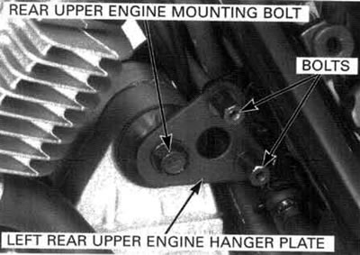
Install the left rear upper engine hanger plate and bolts.
Install the right rear upper engine hanger plate and bolts.
Carefully align the bolt holes in the hanger plates and engine then insert the rear upper engine mounting bolt.
Loosely install the rear upper engine mounting nut.

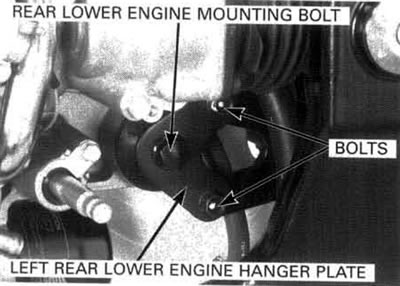
Install the left rear lower engine hanger plate and bolts.
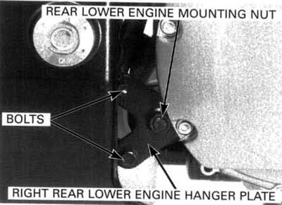
Install the right rear lower engine hanger plate and bolts.
Carefully align the bolt holes in the hanger plates and engine then insert the rear lower engine mounting bolt.
Loosely install the rear lower engine mounting nut.
Install the right front lower engine hanger plate and bolt.
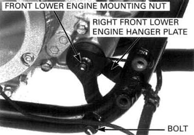
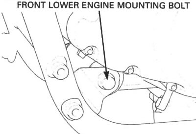
Carefully align the bolt holes in the hanger plates and engine then insert the front lower engine mounting bolt.
Loosely install the front lower engine mounting nut.
Install the left front upper engine hanger plate and bolts.
Install the right front upper engine hanger plate and bolts.
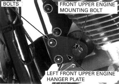
Carefully align the bolt holes in the hanger plates and engine then insert the front upper engine mounting bolt.
Loosely install the front upper engine mounting nut.

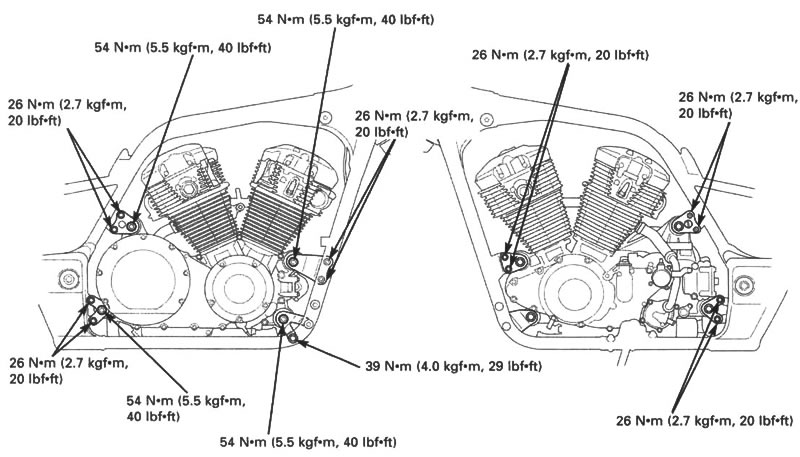
After installing the engine, tighten all engine mounting nuts and hanger plate bolts to the specified torque.
Torque:
- Front upper engine mounting nut: 54 N·m (5.5 kgf·m, 40 lbf·ft)
- Front lower engine mounting nut: 54 N·m (5.5 kgf·m, 40 lbf·ft)
- Rear upper engine mounting nut: 54 N·m (5.5 kgf·m, 40 lbf·ft)
- Rear tower engine mounting nut: 54 N·m (5.5 kgf·m, 40 lbf·ft)
- Right front upper engine hanger plate bolt: 26 N·m (2.7 kgf·m, 20 lbf·ft)
- Left front lower engine hanger plate bolt: 26 N·m (2.7 kgf·m, 20 lbf·ft)
- Right front lower engine hanger plate bolt: 39 N·m (4.0 kgf·m, 29 lbf·ft)
- Rear upper engine hanger plate bolt: 26 N·m (2.7 kgf·m, 20 lbf·ft)
- Rear lower engine hanger plate bolt: 26 N·m (2.7 kgf·m, 20 lbf·ft)
Coat new О-rings with coolant and install them onto the water hose joints.

Connect the water hose joints to the cylinder heads and tighten the bolts securely.

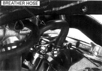
Connect the breather hose from the to cylinder head.
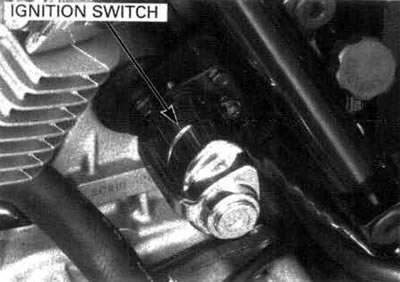
Install the ignition switch (page 19-12).
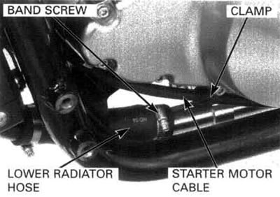
Route the starter motor cable and install it to the starter motor.
Install and tighten the starter motor cable nut to the specified torque.
Torque: 7 N·m (0.7 kgf·m, 5.1 lbf·ft).
Install the radiator mounting bolts (page 6-9).

Install a new О-ring to the water pump pipe.
Install the water pump pipe and tighten the bolts securely.
Connect the lower radiator hose and tighten the band screw securely.
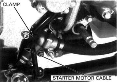
Install the starter motor cable to the clamp.
Install the starter motor cable to the clamp.
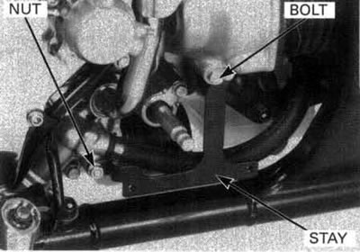
Install the left crankcase rear cover stay and tighten the bolt and nut securely.
Install the PAIR assembly.
Connect the PAIR air hose to the front PAIR reed valve cover.
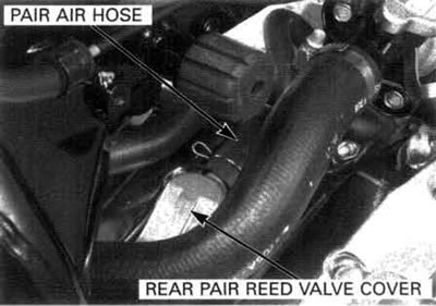
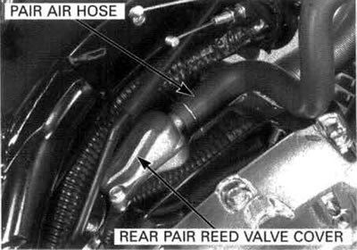
Connect the PAIR air hose to the rear PAIR reed valve cover.
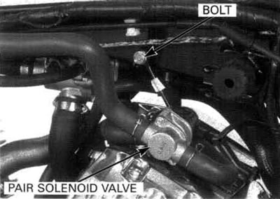
Install the PAIR solenoid valve and tighten the bolt securely.
Connect the PAIR solenoid valve 2P connector.
Install the intake duct control solenoid valve and accumulator.
Install and tighten the bolt securely.
Connect the intake duct control solenoid valve 2P connector.

Connect the following connectors:
- Alternator 3P connector
- Ignition pulse generator 2P connector
- Neutral switch connector
- Oil pressure switch connector
- Speed sensor 3P connector
- Cam pulse generator 2P black connector
- Ground cable on the right crankcase cover
Install the following:
- Front/rear ignition coil (page 17-5)
- Throttle body (page 5-58)
- Fuel tank (page 5-50)
- Left step holder (page 16-12)
- Exhaust system
- Thermostat housing bolt (page 6-12)
Pour the recommended engine oil up to the proper level (page 3-14).
Fill the cooling system with the recommended coolant and bleed any air (page 6-5).