
Removal
Warning! Before starting work, ensure the motorcycie is stabilised and adequately supported. This will help prevent it from falling and causing injury to the operator or damage to the motorcycle.
To gain access to the engine for removal:
1. Raise and securely support the motorcycle and engine.
2. Remove the rider's seat.
3. Disconnect the battery, negative (black) lead first, then remove it as described on page 18.9.
4. Remove the left and right side panels as described on page 17.9.
5. Drain the engine oil as described on page 9.7.
6. Remove the fuel tank as described on page 11.99.
7. Disconnect the throttle cables as described on page 11.116.
8. Remove the exhaust header system as described on page 11.133.
Note: The catalyst box and silencers can remain in place.
9. Remove the radiator as described on page 12.11.
10. Remove the throttle bodies and intake hose as described on page 11.121.
11. Remove the oil tank as described on page 9.16.
12. Remove the rear wheel as described on page 16.8.
13. Remove the swinging arm, bevel box and rear suspension units as described in section 6.
14. Remove the front wheel as described on page 16.6.
15. Remove the front mudguard as described on page 17.10.
16. Remove the rear brake master cylinder heel guard.
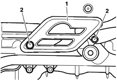
1. Heel guard; 2. Heel guard fixings
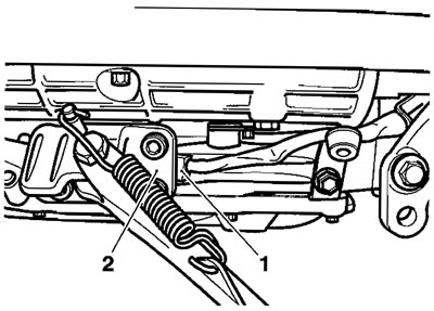
17. Remove the clip from the rear brake pedal clevis pin. Remove the clevis pin.
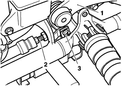
1. Pedal; 2. Pushrod; 3. Clevis
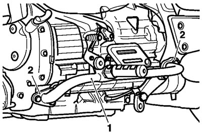
18. Temporarily support the rear brake master cylinder then remove the bolts securing it to the footrest mounting bar.

1. Footrest mounting bar; 2. Master cylinder botts
Note: It is not necessary to disconnect the brake pipe from the master cylinder.
19. Unclip the brake pipe.
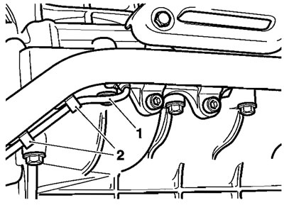
1. Brake pipe; 2. Clips
20. Remove the heat shield from the brake pipe joint.
21. Release the fixing securing the brake pipe joint to the frame outrigger.

1. Brake pipe joint; 2. Bolt
22. Detach the five bolts securing the footrest mounting bar to the frame and crankcase. Detach the bar.
Caution! When repositioning the rear brake master cylinder, take car to prevent the steel brake pipe from becoming distorted.
23. Position the master cylinder, brake pipe and joint in a safe place, preventing the brake fluid reservoir from becoming inverted.
24. Select neutral and note the position of the gear change crank relative to the selector shaft.
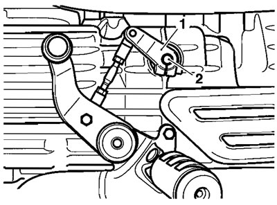
1. Gear change crank; 2. Selector shaft
25. Remove the bolt from the gear change crank. Detach the crank.
26. Release the bolts securing the left hand footrest mounting bar to the frame and engine. Detach the bar.
27. Noting their respective positions, disconnect the spark plug leads from the spark plugs.
28. Disconnect the side stand switch.
29. Remove the side stand complete with its mounting bracket.
1. Side stand switch connections; 2. Side stand bracket
30. Release the clip securing the engine breather hose to the engine. Detach the hose.
31. Disconnect all electrical connections to the engine. These include:
- Low oil pressure warning light switch
- Crankshaft position sensor
- Gear position sensor
- Road speed sensor
- Coolant temperature sensor
- Battery earth
- Starter motor connections
32. Undo the bolts securing the airbox to the frame.
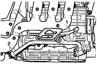
33. Detach the breather hose at the crankcase.
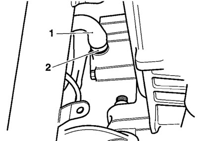
1. Breather hose; 2. Clip
Note: It is not necessary to remove the airbox, but allowing it to float within the frame is helpful.
34. Check that the engine is still securely supported.
35. Undo all engine mounting bolts and nuts, leaving the bolts in place until later.
36. Release the engine mounting adjuster collar and adjusters on the right side of the frame using service tool T3880063.
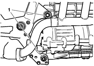
1. Adjuster collars
37. Have several colleagues support the frame, then remove all engine mounting bolts from the engine mountings.
38. Leaving the engine on its support, lift the frame off the engine.
Installation
Note: As the frame is being lowered onto the engine, reconnect the low oil pressure warning light switch and attach the breather hose.
1. Locate the frame to the engine aligning the engine mounting points with the corresponding positions on the frame.
2. Install the engine mounting bolts and nuts, but do not tighten any yet.
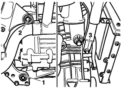
1. Lower rear mounting bolt (one per side); 2. Upper rear mounting bolt (one per side); 3. Front mounting bolt
3. Tighten the engine mounting bolts, nuts, adjusters and adjuster collars in the following sequence:
- Tighten the upper and lower left hand rear engine mounting bolts and nuts to 80 Nm.
- Support the frame and engine, and temporarily remove the rear right hand mounting bolts.
- Tighten the right hand rear adjusters to 5 Nm.
- Refit the rear right hand mounting bolts.
- Tighten the upper and lower rear right hand engine mountings to 80 Nm.
- Using service tool T3880063, tighten the locking collars on both right hand engine mounting adjusters to 55 Nm.
- Tighten the front engine mounting bolt and nut to 80 Nm.
4. Reconnect the remaining electrical connections to the engine. These include:
- Low oil pressure warning light switch
- Crankshaft position sensor
- Gear position sensor
- Road speed sensor
- Coolant temperature sensor
- Battery earth
- Starter motor connections
5. Attach and secure the engine breather hose with its clip.
6. Position the airbox to its mountings, fit and tighten its bolts to 9 Nm.
7. Refit the side stand, tightening the fixings to 40 Nm.
8. Reconnect the side stand switch.
9. Reconnect the spark plug leads.
10. Position the left hand footrest mounting bar to the frame and engine.
11. Fit and tighten the bar's mounting bolts to 27 Nm.
1. Left hand footrest mounting bar; 2. Fixings
12. Position the gear change crank to the selector shaft engaging the splines as noted during removal.
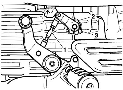
1. Selector rod; 2. Gear change crank; 3. Pinch bolt
13. Fit the pinch bolt to the crank and tighten it to 9 Nm.
14. Support the rear brake master cylinder assembly while aligning the brake pipe joint to the frame outrigger. Tighten the bolt retaining the brake pipe joint to 20 Nm.

1. Brake pipe joint; 2. Fixing
15. Position the right hand footrest mounting bar to the frame and engine.
16. Fit and tighten the bar's mounting bolts to 27 Nm.
1. Right hand footrest mounting bar; 2. Fixings
17. Position the master cylinder to the right hand footrest mounting bar. Fit and tighten the master cylinder bolts to 27 Nm.
18. Align the brake pedal with the pushrod, engage the clevis and retain it with the clip. Ensure the clip is fitted as shown below.
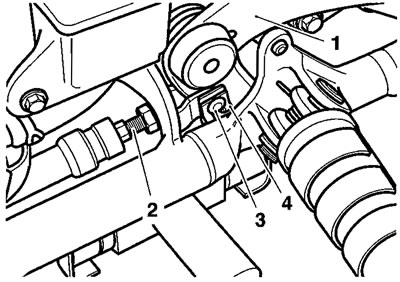
1. Pedal; 2. Pushrod; 3. Clevis; 4. Clip
19. Refit the heel guard tightening the fixings to 9 Nm.
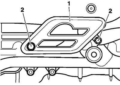
1. Hee) guard; 2. Heel guard fixings
20. Fit the brake pipe to its clip.

1. Brake pipe; 2. Clip
21. Refit the front mudguard as described on page 17.11.
22. Refit the front wheel as described on page 16.7.
23. Refit the swinging arm, bevel box and rear suspension units as described in section 6.
24. Refit the rear wheel as described on page 16.9.
25. Refit the oil tank as described on page 9.16.
26. Refit the throttle bodies and intake hose as described on page 11.122.
27. Reconnect and adjust the throttle cables as described on page 11.117 and 11.118.
28. Refit the radiator as described on page 12.13.
29. Refit the exhaust headers as described on page 11.135.
30. Refit the fuel tank as described on page 11.100.
31. Refill the engine with oil as described on page 9.8.
32. Reconnect the battery, positive (red) lead first.
33. Refit the rider's seat.
34. Lower the motorcycle to the ground and place it on the side stand.
35. Start the engine and check for oil, coolant and any other leaks.
36. Check and adjust the engine oil level.