Warning! The ignition system produces extremely high voltage. Do not touch the spark plugs or stick coils while the engine is running, or you could receive a severe electrical shock.
Caution!
- Do not disconnect the battery leads or any other electrical connections when the ignition switch is on, or while the engine is running. This is to prevent IC igniter damage.
- Do not install the battery backwards. The negative side is grounded. This is to prevent damage to the diodes and IC igniter.
Removal
Remove:
- Fuel Tank (see Fuel System chapter)
- Right Lower Fairing (see Frame chapter)
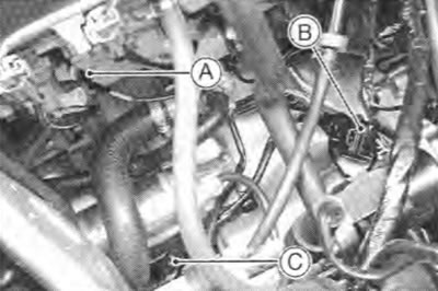
- Water Temperature Sensor Connector [A]
- Pickup Coil Lead Connector [B]
- Side Stand Switch Lead Connector [C]

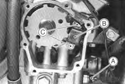
- Neutral Switch Lead Connector [A]

- Pickup Coil Cover
- Oil Pressure Switch Terminal [A]
Remove the pickup coil [B] by taking off the pickup coil bolts [С].

Installation
Route the pickup coil lead correctly (see Cable, Wire, and Hose Routing in General/lnformation chapter).
Install the pickup coil and tighten the pickup coil bolts.
Torque - Pickup Coil Bolts: 5.9 N·m (0.60 kg·m, 52 in·lb)
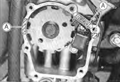
Apply silicone sealant [A] to the pickup coil lead grommet and crankcase halves mating surface on the front and rear sides of the pickup coil cover mount.
Sealant - Kawasaki Bond (Silicone Sealant): 56019-120

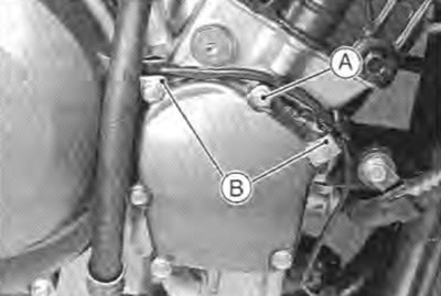
Apply a non-permanent locking agent to the threads of the pickup coil cover bolt [А].
Install the clamps [B] and tighten the pickup coil cover bolts.
Torque - Pickup Coil Cover Bolts: 11 N·m (1.1 kg·m, 95 in·lb)

Install the oil pressure switch terminal and tighten the terminal bolt.
Torque - Oil Pressure Switch Terminal Bolt: 1.5 N·m (0.15 kg·m, 13 in·lb)
Apply grease to the terminal.
Install the other remove parts.
