
Function
Spark generation.
Operating principle
Inductive discharge system.
Level in wiring diagram:coils and injectors.
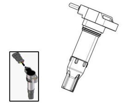
Location:
- on the vehicle: on the cylinder head
- connector (if available): -
Electrical characteristics:
- Primary circuit resistance: approx. 1 Ohm at 20°C between PIN 1 and 3.
- Secondary circuit resistance: MOhm value range (with positive probe on coil).
Pin-out:

1. Supply + batt V; 2. Secondary circuit ground connection; 3. Activation from control unit
Caution! Before carrying out any troubleshooting, carefully read the general troubleshooting concepts for electrical devices at the beginning of the check and control section in the electrical system chapter.
Axone: parameters
Rear coil ignition advance
Front coil ignition advance
Axone: activations
Front coil
The auxiliary injection relay (No. 42 in the wiring diagram, placed under fuel tank, right side, third relay starting from the front; CHECK, however, the identification of the relay with the colour of the cables) is energised for 5 seconds and the sky blue/orange cable of the coil is closed to ground for 2 ms per second. Disconnect the 4-way connector of the fuel pump to be able to hear the relay and injector activation. The continuity of the wiring is necessary for correct activation: no error indications are displayed in case of lack of activation.
Rear coil
The auxiliary injection relay (No. 42 in the wiring diagram, placed under fuel tank, right side, third relay starting from the front; CHECK, however, the identification of the relay with the colour of the cables) is energised for 5 seconds and the sky blue/green cable of the coil is closed to ground for 2 ms per second. Disconnect the 4-way connector of the fuel pump to be able to hear the relay and injector activation. The continuity of the wiring is necessary for correct activation: no error indications are displayed in case of lack of activation.
Axone: electrical errors
Lambda probe P0130 - shorted to positive / circuit, shorted to negative
Error cause
If shorted to positive: excessive voltage has been detected at PIN 17 of the ENGINE connector. If the circuit is open, shorted to negative: voltage equal to zero has been detected at PIN 17 of the ENGINE connector.
Troubleshooting
if shorted to positive: disconnect the coil connector, set the key to ON, activate the coil with Axone and check voltage at connector PIN 3: if there is voltage, restore the cable harness; if voltage = 0, replace the coil. Open circuit, shorted to negative: check the coil connector and the Marelli control unit connector. If not OK, restore; if everything is OK, check cable continuity between the two cable terminals. If there is no continuity, restore the cable harness; if there is cable continuity, with key set to ON, check the cable earth insulation (from coil connector or control unit connector). If not OK, restore the cable harness.
Rear coil P0352 - shorted to positive / open circuit, shorted to negative.
Error cause
If shorted to positive: excessive voltage has been detected at PIN 19 of the ENGINE connector.
If the circuit is open, shorted to negative: voltage equal to zero has been detected at PIN 19 of the ENGINE connector.
Troubleshooting
If shorted to positive: disconnect the coil connector, set the key to ON, activate the coil with Axone and check voltage at connector PIN 3: if there is voltage, restore the cable harness; if voltage = 0, replace the coil.
If the circuit is open, shorted to negative: check the coil connector and the Marelli control unit connector. If not OK, restore; if everything is OK, check cable continuity between the two cable terminals. If there is no continuity, restore the cable harness; if there is cable continuity, with key set to ON, check the cable earth insulation (from coil connector or control unit connector). If not OK, restore the cable harness.