Gearshift fork and gearshift cam
Removal
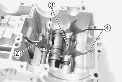
- Remove the gearshift cam bearing retainer screws 1 and gearshift fork shaft retainer plug 2 from the lower crankcase.
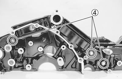
- Remove the gearshift fork shafts 3 and gearshift forks 4 from the lower crankcase.
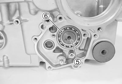
- Remove the gearshift cam 5 and its bearing 6.
Gearshift fork-to-groove clearance
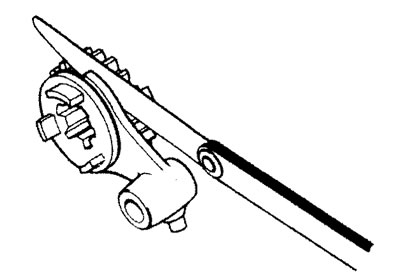
- Using a thickness gauge, check the gearshift fork clearance in the groove of its gear.
- The clearance for each gearshift fork plays an important role in the smoothness and positiveness of the shifting action.
Shift fork-to-groove clearance:
- Service Limit: 0.50 mm (0.020 in)
- 09900-20803: Thickness gauge
- If the clearance checked is noted to exceed the limit specified, replace the fork or its gear, or both.
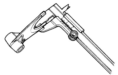
Gearshift fork groove width
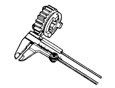
- Measure the gearshift fork groove width using the vernier calipers.
Shift fork groove width:
- Standard: 5.0 - 5.1 mm (0.197 - 0.201 in)
- 09900-20102: Vernier calipers
Gearshift fork thickness
- Measure the gearshift fork thickness using the vernier calipers.
Shift fork thickness:
- Standard: 4.8 - 4.9 mm (0.189 - 0.193 in)
- 09900-20102: Vernier calipers
Gearshift cam bearing and gearshift shaft bearing
Bearing inspection
- Inspect the gearshift cam bearing for abnormal noise and smooth rotation.
- Replace the bearings if there is anything unusual.
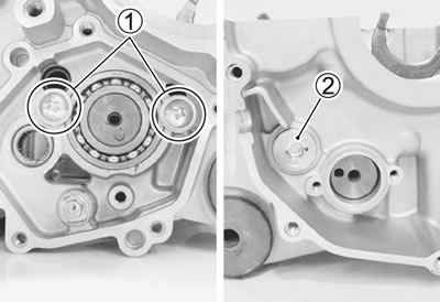
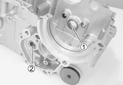
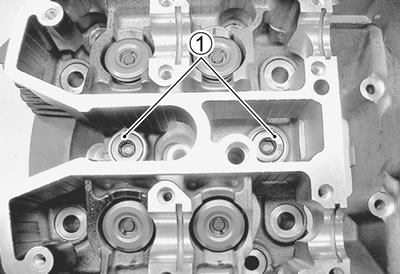
- Inspect the gearshift cam bearing 1, gearshift shaft bearing 2 for abnormal noise and smooth rotation while they are in the crankcase.
- Replace a bearing if there is anything unusual.
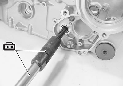
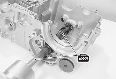
Bearing removal
- Remove the gearshift shaft bearing with the special tools.
- 09921-20210: Bearing remover
- 09930-30104: Sliding shaft
- Remove the gearshift cam bearing with the special tools.
- 09923-74511: Bearing remover
- 09930-30104: Sliding shaft
Installation
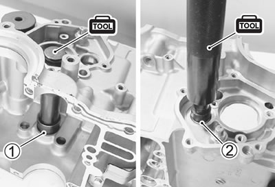
- Install the bearings with the special tool.
- 09913-70210: Bearing installer set (1 ∅20), (2 ∅32)
Note: The stamped mark side of the gearshift shaft bearing 1 and gearshift cam bearing 2 faces outside.
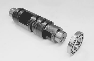
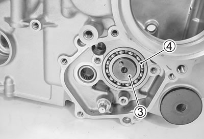
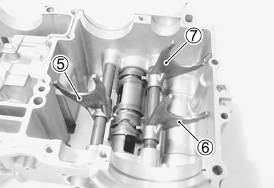
- Install the gearshift cam 3 with the bearing 4.
Note: The stamped mark side of the gearshift cam bearing faces outside.
- Install the gearshift forks and their shafts as shown.
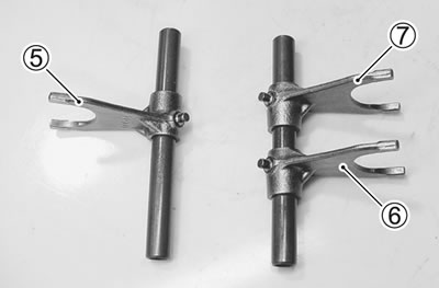
5. For 4th drive gear; 6. For 3rd driven gear; 7. For 5th driven gear
- Apply a small quantity of THREAD LOCK to the bearing retainer screws 8 and gearshift arm stopper bolt 9.
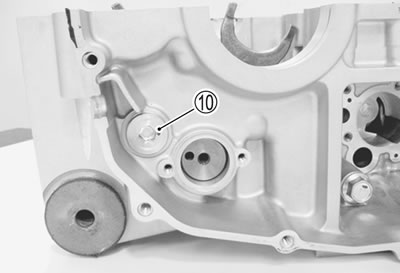
- Tighten the bearing retainer screws 8, gearshift arm stopper bolt 9 and gearshift fork shaft retainer plug 10 to the specified torque.
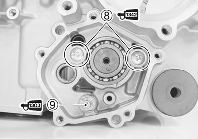
- 99000-32050: THREAD LOCK "1342" or equivalent
- 99000-32030: THREAD LOCK SUPER "1303" or equivalent
- Gearshift arm stopper bolt: 19 Nm (1.9 kgf·m, 13.5 lb·ft)
- Gearshift fork shaft retainer plug: 35 Nm (3.5 kgf·m, 25.5 lb·ft)
Oil jet
Removal
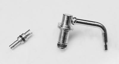
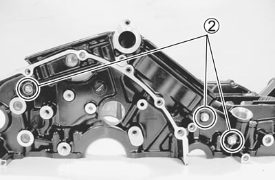
- Remove the piston cooling oil jets 1 and oil jets 2 from the upper crankcase.
- Remove the oil jets 3 (for front and rear cylinder head side).
Inspection and cleaning
- Check the oil jets for clogging.
- Inspect the operation of the oil jet by pushing on the piston with a proper bar
- If they are clogged or piston does not opreat, clean their oil passage with a proper wire and compressed air or replace the oil jet with a new one.
Installation
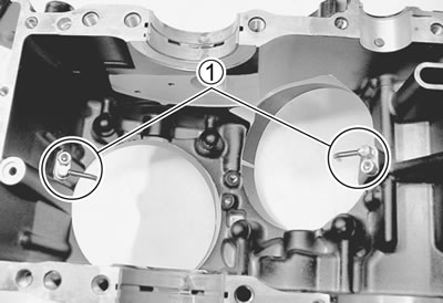
- Fit the new O-ring 1 to each piston cooling oil jet and apply engine oil to them.
Caution: Use the new O-rings to prevent oil pressure leak.
- Install each piston cooling oil jet with the bolt.
Note: Apply a small quantity of THREAD LOCK to the bolts and tighten them.
99000-32050: THREAD LOCK "1342" or equivalent
- Apply engine oil to the new O-ring 2 and 3.
Caution: Use the new O-rings to prevent oil pressure leak.
- Install the oil jet
2. (for upper crankcase side); 3. (for cylinder head side)
Plug
Removal
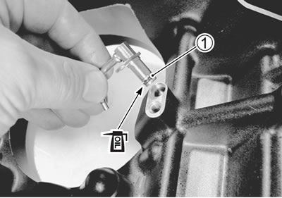
- Remove the water jacket plugs 1 (for front and rear cylinder head side).
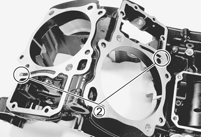
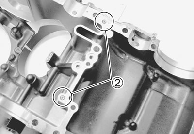
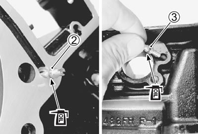
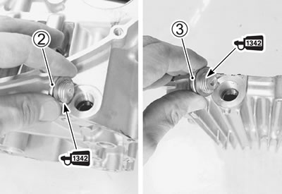
- Remove the oil gallery plugs 2 (for upper crankcase side).
- Remove the oil gallery plugs 2 (for lower crankcase side).
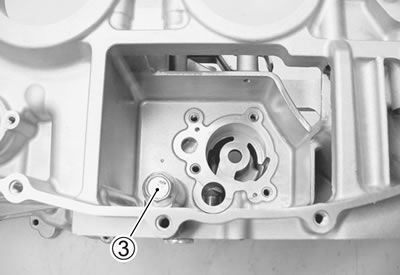
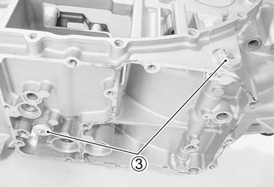
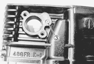
- Remove the oil gallery plugs 3 (for oil pan).
Installation
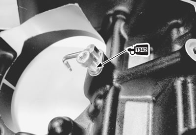
- Apply THREAD LOCK to the water jaket plugoil gallery plugs 1 and oil gallery plugs (2, 3).
- 99000-32050: THREAD LOCK "1342" or equivalent
Note: It is not require to apply THREAD LOCK when installing the other removed oil gallery plugs.
- Tighten each plug to the specified torque.
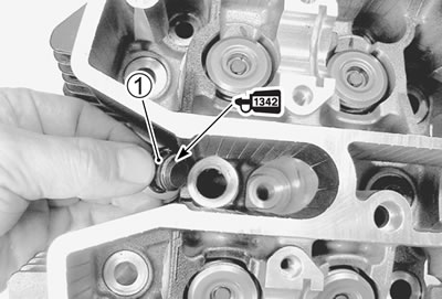
Water jacket plug (cylinder head) 1:
- 26 Nm (2.6 kgf·m, 19.0 lb·ft)
Oil gallery plug (lower crankcase):
- 2: 35 Nm (3.5 kgf·m, 25.5 lb·ft)
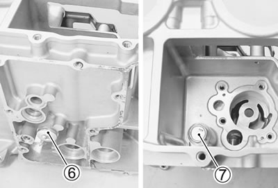
- 6: 25 Nm (2.5 kgf·m, 18.0 lb·ft)
- 7: 21 Nm (2.1 kgf·m, 15.0 lb·ft)
Oil gallery plug (oil pan):
- 3: 35 Nm (3.5 kgf·m, 25.5 lb·ft)
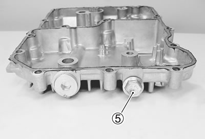
- 5: 16 Nm (1.6 kgf·m, 11.5 lb·ft)
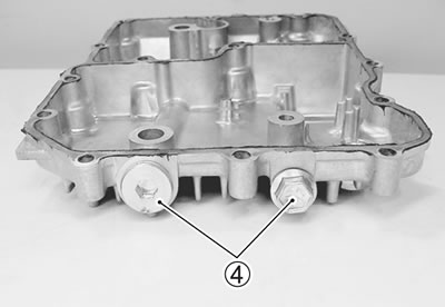
OiI gaIIery pIug (upper crankcase) 4:
- 10 Nm (1.0 kgf·m, 7.0 lb·ft)
Caution: Use each new gasket.