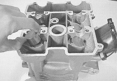
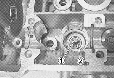
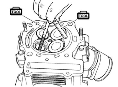
- Remove the tappets and shims (1) by fingers or magnetic hand.
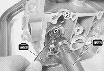
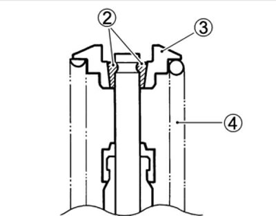
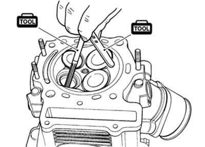
- Using special tools, compress the valve spring and remove the two cotter halves (2) from the valve stem.
- 09916-14510: Valve lifter
- 09916-14910: Valve lifter attachment
- 09916-84511: Tweezers
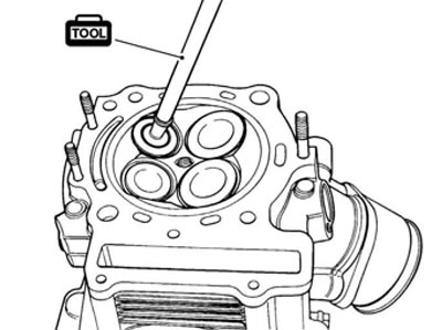
- Remove the valve spring retainer (3) and valve spring (4).
- Pull out the valve from the other side.
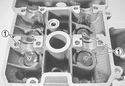
- Remove the oil seals (1) and the spring seats (2)
Caution: Do not reuse the removed oil seals.
Cylinder head distortion
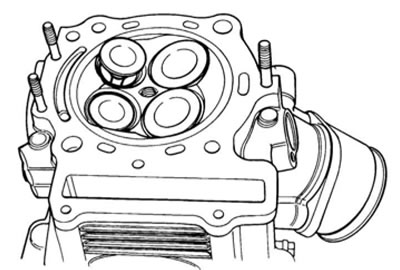
Decarbonize the combustion chambers.
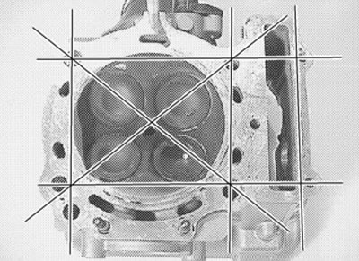
Check the gasketed surface of the cylinder head for distortion with a straightedge and thickness gauge, taking a clearance reading at several places indicated. If the largest reading at any position of the straightedge exceeds the limit, replace the cylinder head.
Cylinder head distortion
- Service Limit: 0.05 mm (0.002 in)
- 09900-20803: Thickness gauge
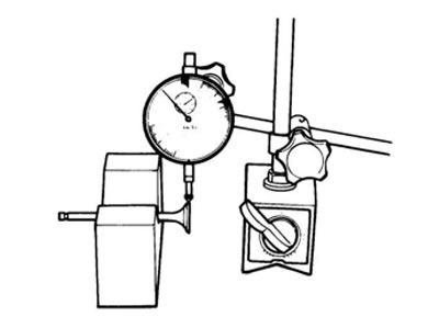
Valve stem runout
Support the valve with "V" blocks, as shown, and check its runout with a dial gauge.
The valve must be replaced if the runout exceeds the limit.
Valve stem runout
- Service Limit: 0.05 mm (0.002 in)
- 09900-20607: Dial gauge (1/100 mm)
- 09900-20701: Magnetic stand
- 09900-21304: V-block (100 mm)
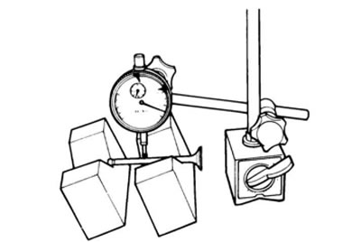
Valve head radial runout
Place the dial gauge at right angles to the valve head face, and measure the valve head radial runout.
If it measures more than the limit, replace the valve.
Valve head radial runout
- Service Limit: 0.03 mm (0.001 in)
- 09900-20607: Dial gauge (1/100 mm)
- 09900-20701: Magnetic stand
- 09900-21304: V-block (100 mm)
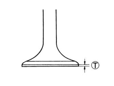
Valve face wear
Visually inspect each valve for wear of its seating face. Replace any valve with an abnormally worn face. The thickness (Т) decreases as the wear of the face advances.
Measure the thickness and, if the thickness is found to have been reduced to the limit, replace it.
Valve head thickness (Т)
- Service Limit: 0.5 mm (0.02 in)
- 09900-20101: Vernier calipers
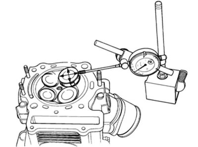
Valve stem deflection
Lift the valve about 10 mm (0.39 in) from the valve seat.
Measure the valve stem deflection in two directions, "X" and "Y", perpendicular to each other, by positioning the dial gauge as shown. If the deflection measured exceeds the limit, (see below) then determine whether the valve or the guide should be replaced with a new one.
Valve stem deflection (IN & EX)
- Service Limit: 0.35 mm (0.014 in)
- 09900-20607: Dial gauge (1/100 mm)
- 09900-20701: Magnetic stand
Valve stem wear
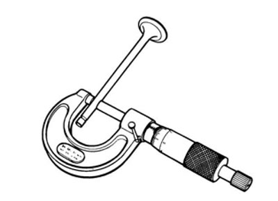
If the valve stem is worn down to the limit, as measured with a micrometer, where the clearance is found to be in excess of the limit indicated, replace the valve; if the stem is within the limit, then replace the guide. After replacing valve or guide, be sure to recheck the clearance.
Valve stem O.D.
- Standard (IN): 5.475-5.490 mm (0.2156-0.2161 in)
- (EX): 5.455-5.470 mm (0.2148-0.2154 in)
- 09900-20205: Micrometer (0-25 mm)
Note: If valve guides have to be removed for replacement after inspecting related parts, carry out the steps shown in valve guide servicing.
Valve guide servicing
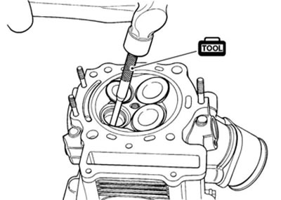
- Using the valve guide remover, drive the valve guide out toward the intake or exhaust camshaft side.
09916-44910: Valve guide remover/installer
Note:
- Discard the removed valve guide subassemblies.
- Only oversized valve guides are available as replacement parts. (Part No.11115-32E70)
- Re-finish the valve guide holes in cylinder head with the reamer and handle.
- 09916-34580: Valve guide reamer
- 09916-34542: Reamer handle
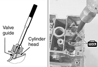
- Oil the stem hole, too, of each valve guide and drive the guide into the guide hole with the valve guide installer and attachment.
- 09916-44910: Valve guide remover/installer
- 09916-53340: Attachment
Caution: Failure to oil the valve guide hole before driving the new guide into place may result in a damaged guide or head.
- After fitting the valve guides, re-finish their guiding bores with the reamer. Be sure to clean and oil the guides after reaming.
- 09916-34550: Valve guide reamer
- 09916-34542: Reamer handle
Note: Insert the reamer from the combustion chamber and always turn the reamer handle clockwise.
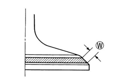
Valve seat width
- Coat the valve seat uniformly with Prussian blue. Fit the valve and tap the coated seat with the valve face in a rotating manner, in order to obtain a clear impression of the seating contact. In this operation, use the valve lapper to hold the valve head.
- The ring-like dye impression left on the valve face must be continuous without any break. In addition, the width of the dye ring, which is the visualized seat "width", must be within the following specification:
Valve seat width (W)
- Standard: 0.9-1.1 mm (0.035-0.043 in)
- 09916-10911: Valve lapper set
If either requirement is not met, correct the seat by servicing is as follows: