
ECU
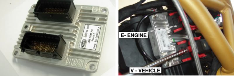
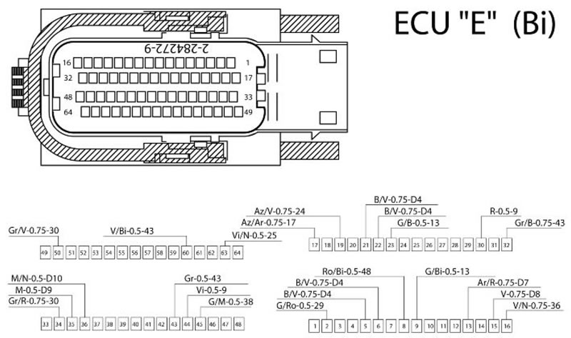
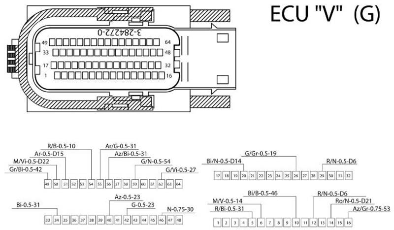
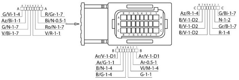
Marelli control unit PIN OUT
| Specification | Desc./Quantity | |
| 1 | Key switch | Vehicle connector: 12/29 |
| 2 | Revolution sensor input (+) | Engine connector: 9 |
| 3 | Revolution sensor input (-) | Engine connector: 23 |
| 4 | Vehicle speed input | Vehicle connector: 49 |
| 5 | Throttle grip input - Track A | Vehicle connector: 42 |
| 6 | Throttle grip input - Track B | Vehicle connector: 40 |
| 7 | Throttle grip input - Track C | Engine connector: 30 |
| 8 | Throttle grip input - Track D | Engine connector: 44 |
| 9 | Front cylinder intake pressure sensor input | Vehicle connector: 34 |
| 10 | Rear cylinder intake pressure sensor input | Vehicle connector: 5 |
| 11 | Water temperature sensor input | Engine connector: 45 |
| 12 | Side stand input | Vehicle connector: 6 |
| 13 | "start engine" input | Vehicle connector: 14 |
| 14 | Clutch sensor input | Vehicle connector: 50 |
| 15 | Fall sensor input | Engine connector: 8 |
| 16 | Gear/neutral input | Engine connector: 16 |
| 17 | Start-up control output | Engine connector: 2 |
| 18 | Serial line K for diagnosis | Vehicle connector: 10 |
| 19 | Auxiliary injection relay control output | Vehicle connector: 62 |
| 20 | Front coil control output | Engine connector: 17 |
| 21 | Rear coil control output | Engine connector: 19 |
| 22 | Front injector control output | Engine connector: 50 |
| 23 | Rear injector control output | Engine connector: 34 |
| 24 | Air temperature sensor input | Engine connector: 63 |
| 25 | Front throttle reset output | Vehicle connector: 56 |
| 26 | Rear throttle reset output | Vehicle connector: 55 |
| 27 | "Engine stop" input | Vehicle connector: 26 |
| 28 | Electric fan relay control output | Vehicle connector: 54 |
| 29 | STOP light relay control output | Vehicle connector: 59 |
| 30 | Lambda heater control output | Engine connector: 32 |
| 31 | Lambda sensor input (+) | Engine connector: 43 |
| 32 | Lambda sensor input (-) | Engine connector: 60 |
| 33 | Purge Canister valve control output (optional) | Engine connector: 51 |
| 34 | Control unit direct power supply | Vehicle connector: 16 |
| 35 | Power ground connection 1 | Engine connector: 21 |
| 36 | Power ground connection 2 | Engine connector: 5 |
| 37 | Power ground connection 3 | Engine connector: 22 |
| 38 | Power ground connection 4 | Engine connector: 6 |
| 39 | Reference voltage output +5V: tracks A-C and pressure sensor | Engine connector: 15 |
| 40 | Reference voltage output +5V: tracks B-D and speed sensor | Engine connector: 13 |
| 41 | Analogue ground connection 1 | Engine connector: 35 |
| 42 | Analogue ground connection 2 | Vehicle connector: 46 Engine connector: 36 |
| 43 | CAN H Line (high speed) | Vehicle connector: 51 |
| 44 | CAN L Line (high speed) | Vehicle connector: 20 |
Note. The connector can be viewed from the cable harness side, that is looking at the cables when going out of the "main" cable harness and into the connector.
Note. The connector can be viewed from the cable harness side, that is looking at the cables when going out of the "main" cable harness and into the connector.
Throttle control unit
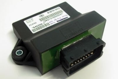
EFI throttle control unit PIN OUT
| Specification | Desc./Quantity | |
| 1 | 1A - Front throttle motor control (-) | Front throttle body PIN: 5 |
| 2 | 2A - CAN L | |
| 3 | 3A - Voltage for front throttle potentiometers (+ 5 V) | Front throttle body PIN: 2 |
| 4 | 4A - Key input | |
| 5 | 5A - Input for front throttle potentiometer 2 signal | Front throttle body PIN: 4 |
| 6 | 6A - Input for front throttle potentiometer 1 signal | Front throttle body PIN: 1 |
| 7 | 7A - Front throttle reset signal input | |
| 8 | 8A - Rear throttle motor control (+) | Rear throttle body PIN: 3 |
| 9 | 1B - Battery power supply input | |
| 10 | 2B- CAN H | |
| 11 | 3B - Voltage for rear throttle potentiometers (+ 5 V) | Rear throttle body PIN: 2 |
| 12 | 4B - Firmware reprogramming power supply | |
| 13 | 5B - Input for rear throttle potentiometer 2 signal | Rear throttle body PIN: 4 |
| 14 | 6B - Input for rear throttle potentiometer 1 signal | Rear throttle body PIN: 1 |
| 15 | 7B - Rear throttle reset signal input | |
| 16 | 8B - Battery power supply input | |
| 17 | 1C - Front throttle motor control (+) | Front throttle body PIN: 3 |
| 18 | 2C - Ground connection | |
| 19 | 3C - Ground connection | Front throttle body PIN: 6 |
| 20 | 4C - Ground connection | Rear throttle body PIN: 6 |
| 21 | 5C - Ground connection | |
| 22 | 6C - Ground connection | |
| 23 | 7C - Ground connection | |
| 24 | 8C - Rear throttle motor control (-) | Rear throttle body PIN: 5 |
Note. The connector can be viewed from the cable harness side, that is looking at the cables when going out of the "main" cable harness and into the connector.
Dashboard
Instrument panel PIN
| Specification | Desc./Quantity | |
| 1 | GREY BODY: + Live | PIN 1 |
| 2 | GREY BODY: Right indicator control | PIN 2 |
| 3 | GREY BODY: * | PIN 3 |
| 4 | GREY BODY: High-beam lights input | PIN 4 |
| 5 | GREY BODY: * | PIN 5 |
| 6 | GREY BODY: Select 3 (Set) | PIN 6 |
| 7 | GREY BODY: Select 2 (Down) | PIN 7 |
| 8 | GREY BODY: Select 1 (Up) | PIN 8 |
| 9 | GREY BODY: Fuel reserve sensor | PIN 9 |
| 10 | GREY BODY: Ambient temperature sensor | PIN 10 |
| 11 | GREY BODY: + Battery | PIN 11 |
| 12 | GREY BODY: Left indicator control | PIN 12 |
| 13 | GREY BODY: Hazard control | PIN 13 |
| 14 | GREY BODY: * | PIN 14 |
| 15 | GREY BODY: * | PIN 15 |
| 16 | GREY BODY: Indicator reset | PIN 16 |
| 17 | GREY BODY: Oil sensor input | PIN 17 |
| 18 | GREY BODY: 750/1200 Selection | PIN 18 |
| 19 | GREY BODY: * | PIN 19 |
| 20 | GREY BODY: K Line | PIN 20 |
| 21 | BLACK BODY: + Battery | PIN 21 |
| 22 | BLACK BODY: Front left turn indicator activation | PIN 22 |
| 23 | BLACK BODY: Front right turn indicator activation | PIN 23 |
| 24 | BLACK BODY: Aerial 2 | PIN 24 |
| 25 | BLACK BODY: * | PIN 25 |
| 26 | BLACK BODY: CAN H | PIN 26 |
| 27 | BLACK BODY: CAN L | PIN 27 |
| 28 | BLACK BODY: ABS warning light input | PIN 28 |
| 29 | BLACK BODY: * | PIN 29 |
| 30 | BLACK BODY: Ground for sensors | PIN 30 |
| 31 | BLACK BODY: + Battery | PIN 31 |
| 32 | BLACK BODY: Rear left turn indicator activation | PIN 32 |
| 33 | BLACK BODY: Rear right turn indicator activation | PIN 33 |
| 34 | BLACK BODY: Aerial 1 | PIN 34 |
| 35 | BLACK BODY: Light relay activation | PIN 35 |
| 36 | BLACK BODY: * | PIN 36 |
| 37 | BLACK BODY: * | PIN 37 |
| 38 | BLACK BODY: General ground | PIN 38 |
| 39 | BLACK BODY: General ground | PIN 39 |
| 40 | BLACK BODY: General ground | PIN 40 |
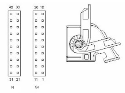
Note. The connector can be viewed from the cable harness side, that is looking at the cables when going out of the "main" cable harness and into the connector.