MotoInstruction.ru
Mobile
version
Articles
& news
Site
map
Feed
back
Add to
bookmark
English Русский
Aprilia
BMW
Ducati
Harley
Honda
Kawasaki
Suzuki
Triumph
Yamaha
Aprilia:
RS-series▾
RS125 [3] (1998-2005)
Shiver▾
SL750 (2007-2016)

Electric fan circuit (Aprilia Shiver 750)

  • Main
  • Aprilia
  • Shiver
  • SL 750
  • Electric equipment
  • Equipment and devices
  • Electric fan circuit
0
Contents: Function ↓ Operating principle ↓

Function


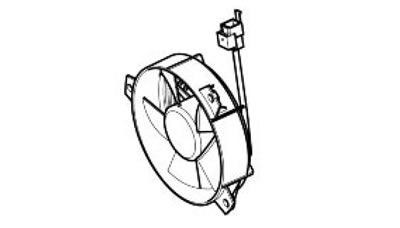
Radiator fan and coolant - Operation.

Operating principle


When the control unit detects a temperature of approx. 102°C, it closes the fan control relay pickup circuit to ground.

Level in wiring diagram: electric fan

Location: the relay is located under the fuel tank, left side, first front relay (CHECK, however, the identification of the relay with the colour of the cables).

Electrical characteristics:
  • relay normally open;
  • drive coil resistance 110 Ohm (+/- 10 %)

drive coil resistance 110 Ohm (+/- 10 %)


Axone: statuses


Fan relay

Example value: on/off

Axone: activations


Fan

The fan relay (No. 44 in the wiring diagram, placed under fuel tank, left side, first front relay; CHECK, however, the identification of the relay with the colour of the cables) is energised for 10 seconds. The continuity of the wiring is necessary for correct activation: no error indications are displayed in case of lack of activation.

Axone: electrical errors


Cooling fan relay P0480 - shorted to positive / shorted to negative / open circuit.

Error cause

If shorted to positive: excessive voltage has been detected at PIN 54 of the VEHICLE connector.


The article is based on materials from the website: motoinstruction.ru

If shorted to negative: short circuit to ground detected.

If the circuit is open: interrupted circuit detected. Excessive voltage can only be detected after the fan relay gets activated.

Troubleshooting

If shorted to positive: check the relay electrical specifications are correct by disconnecting it from the cable harness. If they are not correct, replace the relay; if correct, restore the cable harness (pink/blue cable).

If shorted to negative: check the relay electrical specifications are correct by disconnecting it from the cable harness. If they are not correct, replace the relay; if correct, restore the cable harness (pink/blue cable).

If the circuit is open: check the relay connector and the Marelli control unit VEHICLE connector: If not OK, restore; if OK, restore the cable harness (red/blue cable).
See this article in russian language
This article has been reviewed: Serafim Sazonov
◀ Previous
Aprilia SL750 : Equipment and devices
Next ▶

Instrument panel air temperature sensor
Bank angle sensor/fall sensor
Side stand sensor
Clutch lever sensor
Run / stop switch
Throttle control unit
Connectors pin out
CAN line — function and troubleshooting
Similar articles about motorcycles of other brands
Electric starter circuit Kawasaki ZX6R/ZX600J (2000-2002)
Electric starting system circuit diagram Yamaha FZ1 Fazer (2006-2015)
Electrical circuit inspection procedure Suzuki V-Strom DL-650 (2004-2011)
Oil circuit — description Triumph Rocket III (2004-2018)
Radiator electric fan — removal, disassembly, assembly and… Honda CB 400 SF (1992-1999)
Link to this article in different formats
TEXTHTMLBB Code
Comments and feedback from visitors
No comments yet, you will be the first!


Add up two numbers: 35 + 28


SL750 (2007-2016) 
  • Information for owner
  • Introduction to manual
  • Control devices
  • Operation manual
  • Technical characteristics
  • Maintenance
  • Engine and systems
  • Engine repair
  • Lubrication system
  • Cooling system
  • Fuel system
  • Transmission
  • Running gear and frame
  • Frame and hinged elements
  • Front suspension and handlebar
  • Rear suspension
  • Brake system
  • Electric equipment
  • Equipment and devices
Aprilia BMW Ducati Harley Honda Kawasaki Suzuki Triumph Yamaha
MotoInstruction.ru © 2021–2025 | Sitemap | Articles | Contacts | Site search | Add to bookmarks | Mobile version