
Function
It tells the clutch lever position to the control unit.
Operating principle
If there is gear engaged but the clutch is pulled, i.e. circuit closed to ground, vehicle start-up is not enabled.
Level in wiring diagram: Start-up enabling switches.
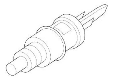
Location:
- on the vehicle: under clutch lever
- connector: on the sensor
Electrical characteristics:
- Clutch pulled: closed circuit (continuity)
- Clutch released: open circuit (infinite resistance)
Pin-out:
- 1. Voltage 12V
- 2. Ground connection
Caution! Before carrying out any troubleshooting, carefully read the general troubleshooting concepts for electrical devices at the beginning of the check and control section in the electrical system chapter.
Axone: statuses
Clutch
Example value: Indefinite - released - pulled
The statuses regularly viewed are Released / Pulled
Troubleshooting
Indication on Axone always Released: check the correct position of the cable terminals on the connector and the correct connection of the cables on the terminals. If they are not correct, restore the cable harness; if correct, disconnect the two terminals from the sensor and, with key set to ON, check continuity to ground connection of PIN 2: if there is no continuity, restore the cable harness; if there is, replace the sensor
Indication on Axone always Pulled: disconnect the terminals from the sensor and check if there is continuity between the two PINS, with clutch released: if there is continuity, replace the sensor. If the circuit is open, it means that the brown/purple cable from sensor PIN 1 to ENGINE connector PIN 50 is shorted to ground: restore the cable harness.