Disconnect plug of ignition lock.
Attach the handlebar to a crane and release the fastener securing the handlebar to the fork bridge.
Remove fasteners (cable ties) securing Bowden cable for starting-speed increase and brake line.
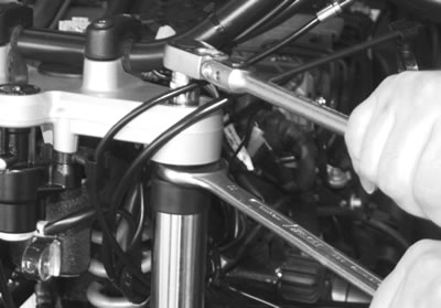
Remove fastener securing fixed tube in upper fork bridge while holding the hexagon of the fixed tube.
Remove fastener securing fork bridge to frame.
Note: The screw pin is a press fit in the angular-contact ball bearing: remove as a complete unit.
Remove fork bridge.
Remove ignition/steering lock.
Installation is the reverse of the removal procedure.
Caution! Align the punch mark on the handlebar with the gap between the clamp blocks.
Tightening torque:
- Fastener securing fork bridge to frame (clean thread + Loctite 243) — 130 Nm
- Fastener securing fork bridge to fixed tube (free from oil and grease) — 45 Nm
- Handlebar to fork bridge — 21 Nm
Removing and installing pot-type joints
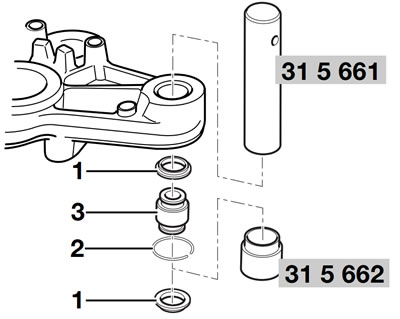
Remove dust covers (1).
Remove snap ring (2).
Press out pot-type joint (3) with mandrel, BMW No. 315661, and sleeve, BMW No. 315662.
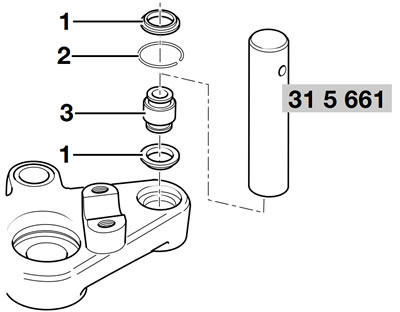
Press in pot-type joint (3) with mandrel, BMW No. 315661.
Install snap ring (2).
Install dust covers (1).
Removing and installing angular-contact ball bearing
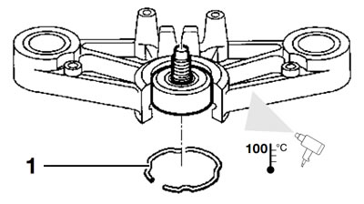
Remove retaining ring(1).
Heat fork bridge to approx. 100°C (212°F).
Remove angular-contact ball bearing, if necessary striking lightly with a plastic-faced hammer.
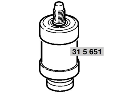
Press out the threaded pin using a mandred, BMW No. 31 5 651, as a support.
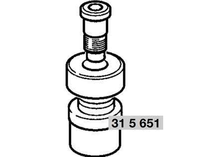
Press the threaded pin into the angular-contact ball bearing using a mandred, BMW No. 31 5 651, as a support.

Heat the fork bridge to 100°C (212°F) and press in the angular-contact ball bearing with pin, BMW No. 31 5 651, and bushing, BMW No. 31 5 653.
Install retaining ring.
