
Headlight
2. If a headlight beam fails to work, first check the fuse (see Section 5), and then the bulb(s) (see Section 7). If they are good, use jumper wires to connect the bulb in question directly to the battery terminals. If the light comes on. the problem lies in the wiring or connectors, the switches in the circuit, or the relay(s) (XRV750 models). Alternatively the bulb can be checked for continuity using a multimeter. Refer to Section 20 for the switch testing procedures, and also to the wiring diagrams at the end of this Chapter.
3. On UK and some European XRV750 models, a relay controls each of the headlight circuits, i.e. one for HI beam, one for LO beam. On other European models there is a HI beam relay only. Refer to the relevant Wiring Diagram at the end of the Chapter for your model, or simply remove the fairing (see Chapter 8), and check to see whether there are two relays or one for the headlights. If a beam does not work and the relay Is suspected of being faulty, the easiest way to tell is to substitute it with the other one (twin relay models) or another one (single relay models) if available. Remove the fairing to access the relay(s) (see illustrations). If the beam then works, the faulty relay must be replaced with a new one. If a substitute is not available, remove the suspect one and test it as follows: set a multimeter to the ohms x 1 scale and connect it across the relay's white/green and white/black (LO BEAM) or blue/yellow (HI beam) wire terminals. There should be no continuity (infinite resistance). Using a fully-charged 12 volt battery and two insulated jumper wires, connect the positive (+) terminal of the battery to the white (LO beam) or blue (HI beam) wire terminal of the relay, and the negative (-) terminal to the green wire terminal. At this point the relay should be heard to click and the meter read 0 ohms (continuity). If this is the case the relay is good. If the relay does not click when battery voltage is applied and indicates no continuity (infinite resistance) across its terminals, it is faulty and must be replaced with a new one.
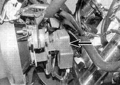
6.3a. HI beam relay (arrowed)

6.3b. LO beam relay (arrowed)
4. If the relay is good, check for battery voltage at the white/green wire terminal on the relay wiring connector with the ignition ON. If there is no voltage, check the wiring between the relay wiring connector and the ignition switch, via the fusebox. then check the switch itself (see Section 19). If voltage is present, check that there is continuity to the headlight wiring connector in the blue or white wire (according to relay), and continuity to earth (ground) in the green wire from the headlight connector. Also check for battery voltage at the white or blue (according to relay) wire terminal on the relay wiring connector with the ignition ON. the light switch ON and the dimmer switch set to LO or HI as required. If voltage is present, check for continuity to earth (ground) in the green wire from the relay wiring connector. Repair or renew the wiring or connectors as necessary.
5. If the low beam does not work on single relay models, check for battery voltage at the white wire terminal on the headlight wiring connector with the ignition ON, the light switch ON and the dimmer switch set to LO. If voltage Is present, check for continuity to earth (ground) in the green wire from the wiring connector. Repair or renew the wiring or connectors as necessary. If there is no voltage, check the wiring, connectors and switches.
Tail light
6. If the tail light fails to work, first check the fuse (see Section 5), and then the bulbs (see Section 9). It they are good, use jumper wires to connect the bulb in question directly to the battery terminals. If the light comes on, the problem lies In the wiring or connectors, or the switches in the circuit. Alternatively the bulb can be checked for continuity using a multimeter. Refer to Section 20 for the switch testing procedures, and also to the wiring diagrams at the end of this Chapter.
7. Check for battery voltage at the brown wire terminal on the tail light wiring connectors with the ignition switch ON. If voltage is present, check for continuity to earth (ground) in the green wire from the wiring connector. If no voltage is indicated, check the wiring and connectors between the tail light and the ignition switch, via the fusebox and the handlebar switch, then check the ignition switch itself (see Section 19).
Brake light
8. If either or both brake lights fail to work, first check the fuse (see Section 5), and then the bulbs (see Section 9). If they are good, use jumper wires to connect the bulb in question directly to the battery terminals. If the light comes on, the problem lies in the wiring or connectors, or the switches in the circuit. Alternatively the bulb can be checked for continuity using a multimeter.
9. Check for battery voltage at the green/yellow wire terminal on the tail light wiring connectors, first with the front brake lever on. then with the rear brake pedal on. If voltage is present with one brake on but not the other, then the switch or its wiring is faulty. If voltage is present in both cases, check for continuity to earth (ground) in the green wire from Ihe wiring connectors. If no voltage Is indicated, check the wiring and connectors between the brake light and the brake switches, the fusebox. and the ignition switch, then check the switches themselves (see Section 14 for the brake light switches and Section 19 for the ignition switch).
Instrument and warning lights
10. See Section 17 for instrument and warning light bulb replacement.
Turn signals
11. See Section 11 for turn signal circuit check.