Self-diagnostic procedure
Place the motorcycle on its side stand.
Start the engine and let it idle.
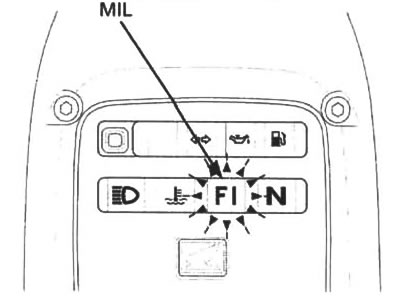
If the malfunction indicator lamp (MIL) does not light or blink, the system has no memory of problem data. If the MIL blinks, note how many times the malfunction indicator blinks, and determine the cause of the problem (page 5-10 through 5-45).

The malfunction indicator will start blinking only with the side stand down and with the engine off (engine stop switch turned to or engine speed below 5.000 rpm In any other condition, the malfunction indicator will illuminate and stay on.
If you wish to read the PGM-FI memory for trouble data, perform the following:
Turn the ignition switch to "OFF".

Remove the seat (page 2-2).
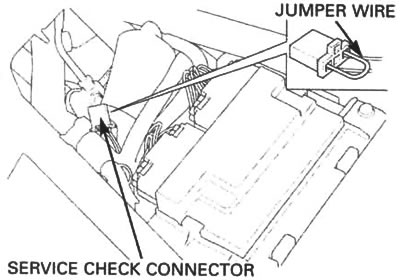
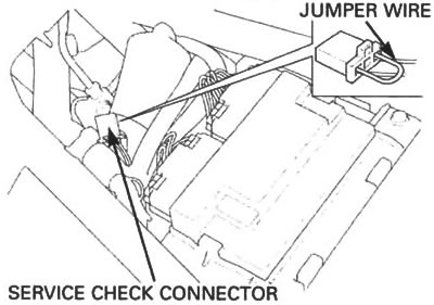
Short the PGM-FI system service check connector terminals using a jumper wire.
Turn the ignition switch to "ON" and engine stop switch to "O".
If the ECM has no self diagnosis memory data, the malfunction indicator will illuminate when you turn the ignition switch to "ON".
If the ECM has self diagnosis memory data, the malfunction indicator will start blinking when you turn the ignition switch to "ON".

Even if the PGM-Fl has memory data, the malfunction indicator does not blink when the engine is running.
Note how many times the MIL blinks, and determine the cause of the problem (page 5-10 through 5-45).

Self-diagnosis reset procedure
1. Turn the engine stop switch to "O" and ignition switch to "OFF".
2. Short the service check connector of the PGM-FI system using a jumper wire.
3. Turn the ignition switch to "ON".
4. Remove the jumper wire from the service check connector.
5. The MIL lights for about 5 seconds.
While the MIL lights, short the service check connector again with the jumper wire.
Self diagnosis memory data is erased, if the malfunction indicator turn off and start blinking.
The service check connector must be jumped while the MIL lights. If not, the MIL will not start blinking.
Note that the self diagnosis memory data cannot be erased if you turn off the ignition switch before the MIL starts blinking.
If the MIL blinks 20 times, the data has not been erased, perform the procedure again.
Peak voltage inspection procedure
Use this procedure for the ignition pulse generator and cam pulse generator inspection.
Check all system connections before inspection. If the system is disconnected, incorrect peak voltage might be measured.
Check cylinder compression and check that all spark plugs are installed correctly.
Use the recommended digital multimeter or a commercially available digital multimeter with an impedance of 10 MΩ/DCV minimum.
The display value differs depending upon the internal impedance of the multimeter.
Disconnect the fuel pump connector before checking the peak voltage.
Open and support the front end of the fuel tank (page 3-4).
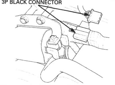
Disconnect the fuel pump 3P black connector.
Connect the peak voltage adaptor to the digital multimeter.
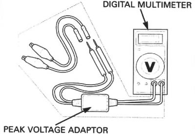
Avoid touching the tester probes to prevent electric shock.
Tools: Peak voltage tester (USA only) or Peak voltage adaptor — 07HGJ-0020100 (not available in USA)
With commercially available digital multimeter (impedance 10 MΩ/DCV minimum).
Test harness connection
Remove the seat (page 2-2).
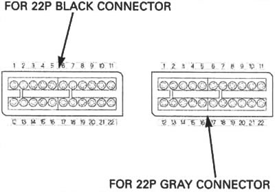
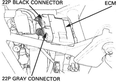
Disconnect the ECM 22P black and 22P gray connectors from the unit.
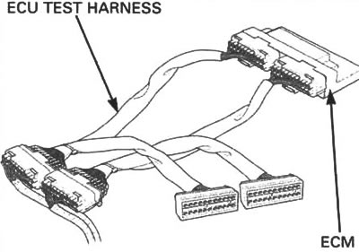
Connect the ECU test harness between the main wire harness and the ECM.
Tool: ECU test harness — 07YMZ-0010100 (two required).
Test harness terminal layout
The ECM connector terminals are numbered as shown in illustration.

The test harness terminals are same layout as for the ECM connector terminals as shown.