
| Turn the ignition switch to "OFF". | ||
| ↓ | ||
Disconnect the MAP sensor 3P black connector. Check for loose or poor contact on the MAP sensor connector. | ||
| ↓ | ||
| Connect the MAP sensor 3P black connector. Place the motorcycle on its side stand. Start the engine and check that the MIL blinks. | Does not blink → | Loose or poor contact on the MAP sensor connector. |
| ↓ | ||
| 1 blink | ||
| ↓ | ||
| Turn the ignition switch to "OFF". | ||
| ↓ | ||
| Disconnect the MAP sensor 3P black connector. Turn the ignition switch to "ON". Measure the voltage at the wire harness side connector. 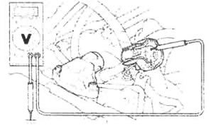 Connection: Yellow/red (+) - Ground (-) Standard: 4.75-5.25 V | Out of range → | Open or short circuit in Yellow/red wire. Loose or poor contact on the ECM connectors. |
| ↓ | ||
| Voltage exists | ||
| ↓ | ||
Measure the voltage between the connector terminals of the wire harness side.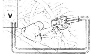 Connection: Yellow/red (+) - Green/orange (-) Standard: 4.75 - 5.25 V | Out of range → | Open or short circuit in Yellow/red wire. Loose or poor contact on the ECM connectors. |
| ↓ | ||
| Voltage exists | ||
| ↓ | ||
| ↓ | ||
Measure the voltage between the terminals of the wire harness side.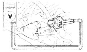 Connection: Light green/yellow (+) - Green/orange (-) Connection: Light green/yellow (+) - Green/orange (-)Standard: 4.75-5.25 V | Out of range → | Open or short circuit in Light green/yellow wire. Loose or poor contact on the ECM connectors. |
| ↓ | ||
| Voltage exists | ||
| ↓ | ||
| Turn the ignition switch to "OFF". Connect the MAP sensor 3P black connector.  | ||
| ↓ | ||
| Disconnect the ECM connectors. Connect the test harness to ECM connectors. Turn the ignition switch to "ON".  | ||
| ↓ | ||
Measure the voltage at the test harness terminals (page 5-9). Connection: B7 (+) - B1 (-) Standard: 2.7 - 3.1 V (760 mm Hg/1,013 kPa) | Out of range → | Faulty MAP sensor. |
| ↓ | ||
| Voltage exists | ||
| ↓ | ||
| Replace the ECM with a new one, and inspect it again. |
Honda:
PGM-FI MIL 1 blink (MAP sensor) (Honda VTX series VTX 1800 C)
See this article in russian language
PGM-FI self-diagnosis malfunction indicator failure codes
PGM-FI (programmed fuel injection) system
Fuel system diagram
Fuel system location
Troubleshooting of fuel system
Service information of fuel system
PGM-FI (programmed fuel injection) system
Fuel system diagram
Fuel system location
Troubleshooting of fuel system
Service information of fuel system
PGM-FI MIL 2 blinks (MAP sensor)
PGM-FI MIL 7 blinks (ECT sensor)
PGM-FI MIL 8 blinks (TP sensor)
PGM-FI MIL 9 blinks (IAT sensor)
PGM-FI MIL 10 blink (BARO sensor)
PGM-FI MIL 11 blinks (vehicle speed sensor)
PGM-FI MIL 12 blinks (rear injector)
PGM-FI MIL 13 blinks (front injector)
PGM-FI MIL 18 blinks (cam pulse generator)
PGM-FI MIL 19 blinks (ignition pulse generator)
Similar articles about motorcycles of other brands
Suzuki DR-Z DRZ-250 1996-2007: Peak voltage on sensor winding and signal winding
Triumph Rocket III 2004-2018: Crankshaft sensor — pinpoint tests
Yamaha Fazer FZ1 2006-2015: Removing the crankshaft position sensor
Kawasaki ZX-6R ZX600-J1/J2 2000-2002: Non-contact hall IC-Type speed sensor
Harley V-Rod VRSCA 2002-2006: Throttle position sensor: TP
BMW R-series R 1150 GS 1999-2004: Removing and installing fuel filter, fuel pump and fuel level sensor
Ducati ST series ST2 1997-2003: Testing the engine sensor air gap
Aprilia Shiver SL 750 2007-2016: Removing the lambda sensor
Link to this article in different formats
TEXTHTMLBB Code
Comments and feedback from visitors
No comments yet, you will be the first!
- Information for owner
- Control devices
- Operation manual
- Maintenance
- Engine and systems
- Engine repair
- Fuel and control system
- Cooling system
- Lube system
- Transmission
- Running gear and frame
- Frame and hinged elements
- Front suspension and handlebar
- Rear suspension
- Brake system
- Electric equipment
- Equipment and devices
- Ignition system
- Starting and charging system
Aprilia: RS-series Shiver (map) BMW: F-series R-series K-series (map) Ducati: ST series Monster (map) Harley: Street Sportster V-Rod (map) Honda: Africa Twin CB series VTX series (map) Kawasaki: ZX-6R Versys Vulcan (map) Suzuki: DR-Z V-Strom Boulevard (map) Triumph: Rocket Street Triple (map) Yamaha: Fazer DragStar R1 (map)