
| Turn the ignition switch to "OFF". | ||
| ↓ | ||
| Disconnect the front injector 2P brown connector. Check for loose or poor contact on the front injector 2P gray connector. 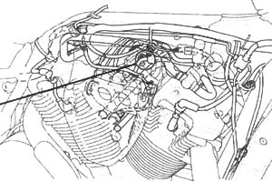 | ||
| ↓ | ||
| Connect the front injector 2P gray connector. Place the motorcycle on its side stand. Turn the ignition switch to "ON". Check that the MIL blinks. 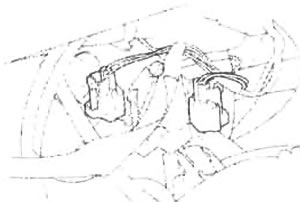 | Does not blink → | Loose or poor contact on the front injector 2P gray connector. |
| ↓ | ||
| 12 blinks | ||
| ↓ | ||
| Turn the ignition switch to "OFF". Disconnect the front injector 2P gray connector and measure the resistance of the front injector. 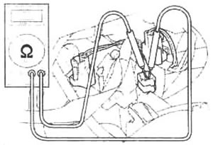 Connection: Black/white ( + ) - Pink/blue (-) Standard: 11.1-12.3 Ω (20°C/68°F) | Abnormal → | Faulty front injector. |
| ↓ | ||
| Normal | ||
| ↓ | ||
Check for continuity between the front injector and ground.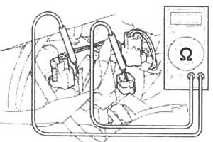 Connection: Black/white (+) - Ground (-) Standard: No continuity | Continuity → | Faulty front injector. |
| ↓ | ||
| No continuity | ||
| ↓ | ||
| Turn the ignition switch to "ON". Measure the voltage between the front injector 2P gray connector of the wire harness side and ground. 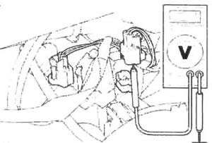 Connection: Black/white (+) - Ground (-) Connection: Black/white (+) - Ground (-)Standard: Battery voltage | Out of range → | Open or short circuit in the Black/white wire. |
| ↓ | ||
| Voltage exists | ||
| ↓ | ||
| Turn the ignition switch to "OFF". Connect the front injector 2P gray connector.  | ||
| ↓ | ||
| Disconnect the ECM connectors. Connect the test harness to the wire harness connectors.  | ||
| ↓ | ||
Measure the resistance at the test harness terminals.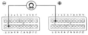 Connection: A13 (-) - B2 (+) Standard: 9-15 Ω (20°C/68°F) | Out of range → | Open circuit in the Black/white and/or Pink/yellow wire. |
| ↓ | ||
| Normal | ||
| ↓ | ||
Check for continuity between the test harness terminal and ground.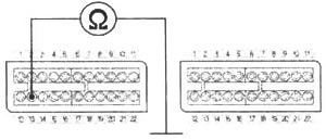 Connection: A13 - Ground Standard: No continuity | Continuity → | Short circuit in the Pink/yellow wire. |
| ↓ | ||
| No continuity | ||
| ↓ | ||
| Replace the ECM with a new one, and inspect it again. |
Honda:
PGM-FI MIL 13 blinks (front injector) (Honda VTX1800C)
See this article in russian language
PGM-FI MIL 12 blinks (rear injector)
PGM-FI MIL 11 blinks (vehicle speed sensor)
PGM-FI MIL 10 blink (BARO sensor)
PGM-FI MIL 9 blinks (IAT sensor)
PGM-FI MIL 8 blinks (TP sensor)
PGM-FI MIL 7 blinks (ECT sensor)
PGM-FI MIL 2 blinks (MAP sensor)
PGM-FI MIL 1 blink (MAP sensor)
PGM-FI self-diagnosis malfunction indicator failure codes
PGM-FI (programmed fuel injection) system
PGM-FI MIL 18 blinks (cam pulse generator)
PGM-FI MIL 19 blinks (ignition pulse generator)
PGM-FI MIL 21 blinks (O2 sensor/California type only)
PGM-FI MIL 23 blinks (O2 sensor heater/California type only)
PGM-FI MIL 33 blinks (E2-prom)
Fuel pressure inspection
Fuel flow inspection
Fuel pump — removal and installation
Fuel cut-off relay
Fuel tank — removal and installation
Similar articles about motorcycles of other brands
Suzuki DR-Z DRZ-250 1996-2007: Front brake hose routing
Triumph Rocket III 2004-2018: Exploded view — front fork
Yamaha Fazer FZ1 2006-2015: Front fork adjustment
Kawasaki ZX-6R ZX600-J1/J2 2000-2002: Front wheel — removal and installation
Harley V-Rod VRSCA 2002-2006: Replacing front fork oil
BMW R-series R 1150 GS 1999-2004: Bleeding front brake circuit/changing brake fluid
Ducati ST series ST2 1997-2003: Checking front brake pad wear, changing brake pads
Aprilia RS-series RS 125 1999-2005: Positioning the vehicle on the front service stand (OPT)
Link to this article in different formats
TEXTHTMLBB Code
Comments and feedback from visitors
No comments yet, you will be the first!
- Information for owner
- Control devices
- Operation manual
- Maintenance
- Engine and systems
- Engine repair
- Fuel and control system
- Cooling system
- Lube system
- Transmission
- Running gear and frame
- Frame and hinged elements
- Front suspension and handlebar
- Rear suspension
- Brake system
- Electric equipment
- Equipment and devices
- Ignition system
- Starting and charging system
Aprilia: RS-series Shiver (map) BMW: F-series R-series K-series (map) Ducati: ST series Monster (map) Harley: Street Sportster V-Rod (map) Honda: Africa Twin CB series VTX series (map) Kawasaki: ZX-6R Versys Vulcan (map) Suzuki: DR-Z V-Strom Boulevard (map) Triumph: Rocket Street Triple Tiger (map) Yamaha: Fazer DragStar R1 (map)