
| Turn the ignition switch to "OFF". | ||
| ↓ | ||
| Disconnect the TP sensor 3P gray connector. Check for loose or poor contact on the TP sensor 3P gray connector. 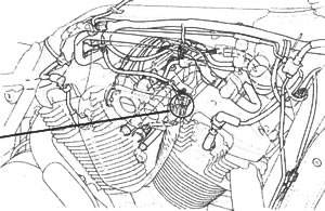 | ||
| ↓ | ||
| Connect the TP sensor 3P gray connector. Place the motorcycle on its side stand. Start the engine and check that the MIL blinks. 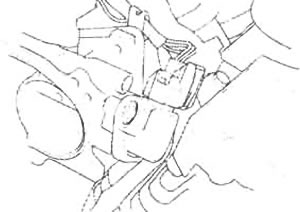 | Does not blink → | Loose or poor contact on the TP sensor 3P gray connector. |
| ↓ | ||
| 8 blinks | ||
| ↓ | ||
| Turn the ignition switch to "OFF". | ||
| ↓ | ||
| Disconnect the TP sensor 3P gray connector. Turn the ignition switch to "ON". Measure the voltage between the wire harness side connector terminal and ground. 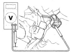 Connection: Yellow/red (+) - Ground (-) Standard: 4.75-5.25 V | Out of range → | Open or short circuit in the Yellow/red wire. Loose or poor contact on the ECM connector. |
| ↓ | ||
| Voltage exists | ||
| ↓ | ||
Measure the voltage at the TP sensor terminals of the wire harness side.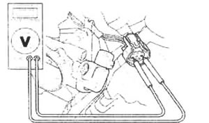 Connection: Yellow/red (+) - Green/orange (-) Standard: 4.75-5.25 V | Out of range → | Open or short circuit in the Green/orange wire. Loose or poor contact on the ECM connectors. |
| ↓ | ||
| Voltage exists | ||
| ↓ | ||
| Turn the ignition switch to "OFF". Disconnect the ECM 22P connectors. 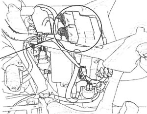 | ||
| ↓ | ||
Check for continuity between the TP sensor 3P gray connector terminal of the wire harness side and ground.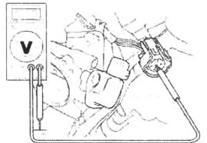 Connection: Red/yellow (+) - Ground (-) Standard: No continuity | Continuity → | Short circuit in the Red/yellow wire. |
| ↓ | ||
| No continuity | ||
| ↓ | ||
Connect the test harness to the ECM connectors.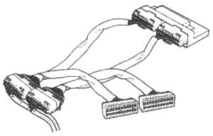 | ||
| ↓ | ||
Check for continuity between the test harness terminal and the TP sensor 3P gray connector terminal.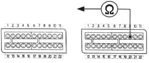 Connection: Red/yellow - B9 Standard: Continuity | No continuity → | Open or short circuit in the Red/yellow wire. |
| ↓ | ||
| Continuity | ||
| ↓ | ||
Connect the TP sensor 3P gray connector. | ||
| ↓ | ||
| Turn the ignition switch to "ON". Measure the voltage at the test harness terminals.  Connection: B9 (+) - B1 (-) Standard: *0.4-0.6 V (throttle fully closed) *4.2-4.8 V (throttle fully open) | Normal → | Replace the ECM with a new one, and inspect it again. |
| ↓ | ||
| Out of range | ||
| ↓ | ||
| Faulty TP sensor. |
A voltage marked * refers to the value when the voltage reading at the TP sensor 3P connector shows 5 V. When the reading shows other than 5 V, derive a voltage at the test harness as follows:
In the case of a voltage of 4.75 V at the TP sensor 3P connector:
- 0.4 x 4.75/5.0 = 0.38 V
- 0.6 x 4.75/5.0 = 0.57 V
Thus, the solution is "0.38 - 0.57 V" with the throttle fully closed.
Replace 0.4 and 0.6 with 4.2 and 4.8 respectively, in the above equations to determine the throttle fully open range.