
| Turn the ignition switch to "OFF". | ||
| ↓ | ||
| Disconnect the ignition pulse generator 2P connector. Check for loose or poor contact on the ignition pulse generator 2P connector.  | ||
| ↓ | ||
| Connect the ignition pulse generator 2P connector. Place the motorcycle on its side stand. Turn the ignition switch to "ON" and check that the MIL blinks. | Does not blink → | Loose or poor contact on the ignition pulse generator 2P connector. |
| ↓ | ||
| 19 blinks | ||
| ↓ | ||
| Turn the ignition switch to "OFF" and the engine stop switch to "O". Disconnect the ignition pulse generator 2P connector.  | ||
| ↓ | ||
Check the continuity between the ignition pulse generator connector terminal and ground.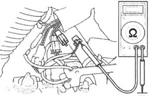 Connection: White/yellow - Ground Standard: No continuity | Abnormal → | Faulty ignition pulse generator. |
| ↓ | ||
| No continuity | ||
| ↓ | ||
Crank the engine with the starter motor, and measure the ignition pulse generator peak voltage at the ignition pulse generator 2P connector.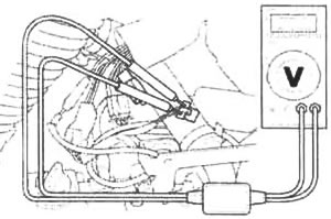 Connection: Yellow (+) - White/yellow (-) Standard: 0.7 V minimum (20°C/68°F) | Out of range → | Faulty ignition pulse generator. |
| ↓ | ||
| Normal | ||
| ↓ | ||
| Connect the ignition pulse generator 2P connector. Disconnect the ECM connectors. Connect the test harness to ECM connectors. 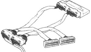 | ||
| ↓ | ||
Crank the engine with the starter motor, and measure the ignition pulse generator peak voltage at the test harness terminals. Connection: B22 (+) - Ground (-) Standard: 0.7 V minimum (20°C/68°F) | Out of range → | Open circuit in the White/yellow wire. Open circuit in the Yellow wire. |
| ↓ | ||
| Normal | ||
| ↓ | ||
| Replace the ECM with a new one, and inspect it again. |
Honda:
PGM-FI MIL 19 blinks (ignition pulse generator) (Honda VTX1800C)
See this article in russian language
PGM-FI MIL 18 blinks (cam pulse generator)
PGM-FI MIL 13 blinks (front injector)
PGM-FI MIL 12 blinks (rear injector)
PGM-FI MIL 11 blinks (vehicle speed sensor)
PGM-FI MIL 10 blink (BARO sensor)
PGM-FI MIL 9 blinks (IAT sensor)
PGM-FI MIL 8 blinks (TP sensor)
PGM-FI MIL 7 blinks (ECT sensor)
PGM-FI MIL 2 blinks (MAP sensor)
PGM-FI MIL 1 blink (MAP sensor)
PGM-FI MIL 21 blinks (O2 sensor/California type only)
PGM-FI MIL 23 blinks (O2 sensor heater/California type only)
PGM-FI MIL 33 blinks (E2-prom)
Fuel pressure inspection
Fuel flow inspection
Fuel pump — removal and installation
Fuel cut-off relay
Fuel tank — removal and installation
Air cleaner housing — removal and installation
Throttle body removal
PGM-FI MIL 23 blinks (O2 sensor heater/California type only)
PGM-FI MIL 33 blinks (E2-prom)
Fuel pressure inspection
Fuel flow inspection
Fuel pump — removal and installation
Fuel cut-off relay
Fuel tank — removal and installation
Air cleaner housing — removal and installation
Throttle body removal
Similar articles about motorcycles of other brands
Suzuki DR-Z DRZ-250 1996-2007: Generator stator and winding maintenance
Triumph Rocket III 2004-2018: Ignition system safety precautions
Yamaha Fazer FZ1 2006-2015: Ignition switch and steering lock
Kawasaki ZX-6R ZX600-J1/J2 2000-2002: Ignition system circuit
Harley V-Rod VRSCA 2002-2006: Ignition switch
BMW R-series R 1150 GS 1999-2004: Removing and installing ignition switch/steering lock
Ducati ST series ST2 1997-2003: Ignition system — description and specification
Aprilia RS-series RS 125 1999-2005: Removing the ignition switch/steering lock
Link to this article in different formats
TEXTHTMLBB Code
Comments and feedback from visitors
No comments yet, you will be the first!
- Information for owner
- Control devices
- Operation manual
- Maintenance
- Engine and systems
- Engine repair
- Fuel and control system
- Cooling system
- Lube system
- Transmission
- Running gear and frame
- Frame and hinged elements
- Front suspension and handlebar
- Rear suspension
- Brake system
- Electric equipment
- Equipment and devices
- Ignition system
- Starting and charging system
Aprilia: RS-series Shiver (map) BMW: F-series R-series K-series (map) Ducati: ST series Monster (map) Harley: Street Sportster V-Rod (map) Honda: Africa Twin CB series VTX series (map) Kawasaki: ZX-6R Versys Vulcan (map) Suzuki: DR-Z V-Strom Boulevard (map) Triumph: Rocket Street Triple Tiger (map) Yamaha: Fazer DragStar R1 (map)