EXCVA and EXCV removal
- Turn the ignition switch OFF.
- Remove the left frame side cover. (9-5)
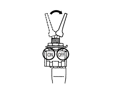
- Connect the special tool (Mode select switch) to the dealer mode coupler. (5-18)
- After turning the special tool's switch ON, turn the ignition switch ON.
- 09930-82720: Mode select switch
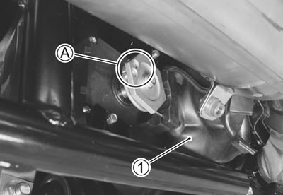
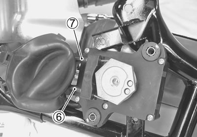
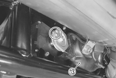
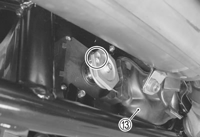
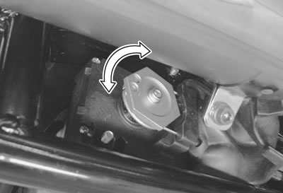
- Remove the rubber cover 1.
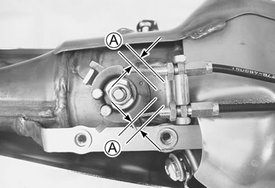
- Check the cable slots А of the EXCVA pulley face backward (adjustment position) as shown.
- Turn the ignition switch OFF.
Caution: Before removing the EXCVA, be sure to set the EXCVA pulley to the adjustment position.
- Remove the exhaust pipe and muffler. (7-8)
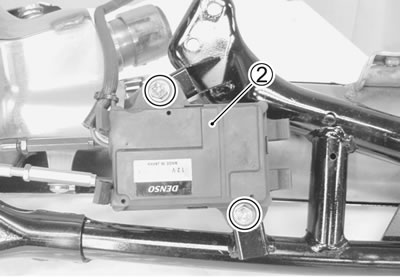
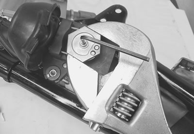
- Remove the EXCVA cover 2.
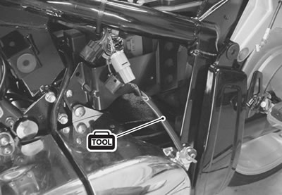
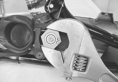
- Hold the EXCVA pulley with an adjustable wrench, and loosen the pulley mounting bolt.
Caution:
- When loosening or tightening the pulley bolt, be sure to fix the pulley with an adjustable wrench, or EXCVA may get damaged.
- Do not use the adjustable wrench to turn EXCVA pulley so as not to cause damage to the internal gear of EXCVA.
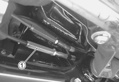
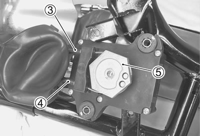
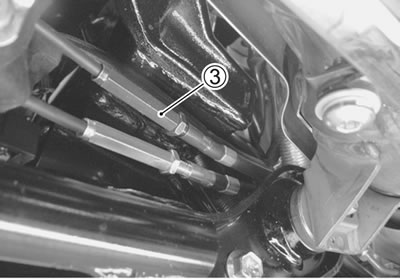
- Disconnect the No. 2 cable 3 and then No. 1 cable 4 from the pulley.
- Remove the EXCVA 5.
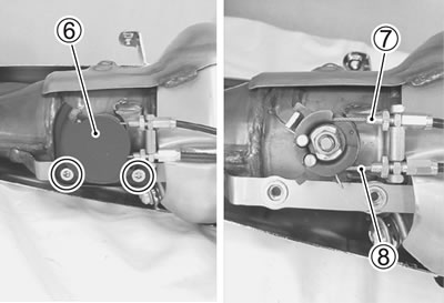
- Remove the EXCV cover 6 from the EXCV pulley.
- Disconnect the No. 1 7 and No. 2 8 cables.
EXCVA Inspection (5-83).
EXCV Inspection
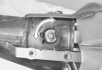
- Turn the EXCV by hand and check that it moves smoothly.
- If it does not move smoothly, replace the EXCV together with the muffler body.
- Decarbonize the EXCV if necessary.
Caution:
- Do not attempt to disassemble the EXCV.
- The EXCV is available only as the muffler body assembly.
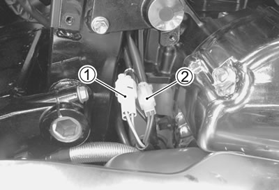
Cable inspection
- Inspect the cables for wear or bend if it is damaged, replace it with a new one.
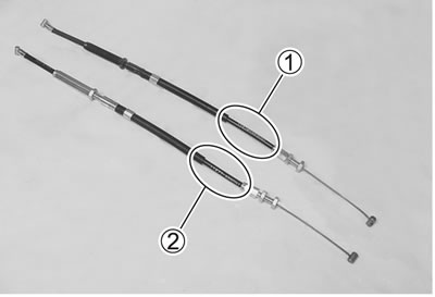
Note: The EXCV cables are identified by the plated chrome color and shape.
- No. 1 cable 1: 11276-48G0
- No. 2 cable 2: 11277-48G0
EXCVA and EXCV Installation
Install the EXCVA and EXCV in the reverse order of removal.
Pay attention to the following points:
- Connect the EXCV cables temporarily to the EXCV pulley.
- Adjust the clearance А between the adjuster end and EXCV pulley to provide 4 mm (0.16 in) and more.
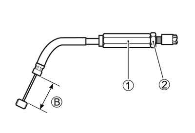
- Make the No. 1 cable straight and turn the No. 1 cable adjuster 1 in or out until the inner cable length В becomes 42 - 43 mm (1.65 - 1.69 in).
- After adjusting the inner cable length В, tighten the lock nut 2.
No. 1 cable: 11276-48G0
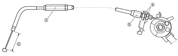
- Make the No. 2 cable straight and turn in the cable adjuster 3 fully.
No. 2 cable: 11277-48G0
- Loosen the lock nuts 4 and turn the No. 2 cable adjuster 5 in or out until the inner cable length С becomes 58 - 59 mm (2.28 - 2.32 in).
- After adjusting the inner cable length С, tighten the lock nuts 4.
- Connect the No. 1 cable 6 and No. 2 cable 7 to the EXCVA pulley.
- Check the EXCVA to adjustment position. (7-2)
Caution: Do not use the adjustable wrench to turn EXCVA pulley so as not to cause damage to the internal gear of EXCVA.
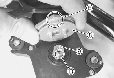
- Install the pulley 8 to the shaft 9.
Note: Make sure that the shaft's line D and cable slots E facing upward as shown.
- Hold the EXCVA pulley with an adjustable wrench, and then tighten the pulley mounting bolt to the specified torque.
EXCVA pulley mounting bolt: 5 N·m (0.5 kgf·m, 3.5 lb-ft)
Caution: When loosening or tightening the pulley bolt, be sure to fix the pulley with an adjustable wrench, or EXCVA may get damaged.
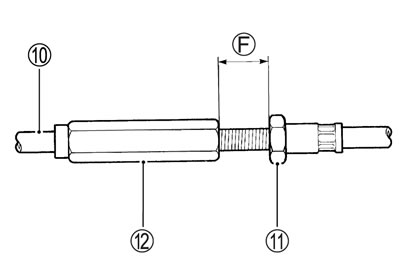
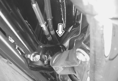
- After connecting the No. 2 cable 10, loosen the lock nut 11 and turn the adjuster 12 in or out until 8.5 - 9.5 mm (0.33 - 0.37 in) of the thread length F on the cable adjuster cam be provided and tighten the lock nut 11.
Caution: The cable slots of the EXCVA pulley must be located backward (adjustment position). (7-2)
Note: Install the rubber cover 13 correctly after inspecting it.
EXCVA Adjustment
1st step:
- Set the EXCVA to adjustment position. (7-2)
- Make sure that the No. 2 cable and No. 1 cable are fixed into the clamp.
2nd step:
- Turn the mode select switch OFF.
- Turn the ignition switch ON to check the EXCVA operation.
- Turn the mode select switch ON.
- If C46 is not indicated on the LCD (DISPLAY), the adjustment is correctly completed. In this case, it is unnecessary to proceed to 3rd step.
- If C46 is indicated, repeat the adjustment procedure from 3rd and 4th step.
3rd step:
- This procedure is only required when C46 is indicated.
- Turn the ignition switch OFF.
- Remove the lower frame cover. (7-8)
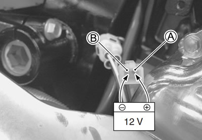
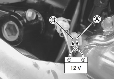
- Insert the two copper wires into the back side of the position sensor lead wire coupler 1.
- Disconnect the EXCVA motor lead wire coupler 2.
- To set the EXCV to fully close position, apply 12 volts to A and B terminals.
- Positive wire — A (Pink wire) terminal
- Negative wire — B (Gray wire) terminal
Caution: To prevent the motor damage, stop applying 12 V as soon as the EXCV reaches fully close position.
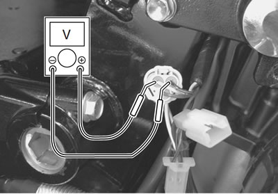
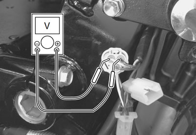
- Turn the ignition switch ON.
- Measure the position sensor output voltage at fully close position.
Position sensor output voltage:
- EXCV is fully close: 0.5 ≤ output voltage ≤ 1.5 V (+ Yellow - − B/Br)
- 09900-25008: Multi circuit tester set
- 09900-25009: Needle pointed probe set
- Tester knob indication: Voltage
If the measured voltage is less than specification, adjust the No.1 cable adjuster as follows:
- Set the EXCVA to adjustment position. (7-2)
Caution: Adjusting the No. 1 cable with the EXCV fully closed can damage the EXCVA. Be sure to adjust the No.1 cable with the EXCV set in adjustment position.
- Turn out the No. 1 cable adjuster 3.
- Repeat the above procedure until the output voltage becomes specified value.
Position sensor output voltage:
- EXCV is fully close: 0.5 ≤ output voltage ≤ 1.5 V
- To next step.
Note: If C46 code is indicated after adjusting the voltage, increase the voltage to 0.9 V.
4th step:
- To set the EXCV to fully open position, apply 12 volts to A and B terminals.
- Positive wire — B (Gray wire) terminal
- Negative wire — A (Pink wire) terminal
Caution: To prevent the motor damage, stop applying 12 V as soon as the EXCV reaches fully open position.
Measure the position sensor output voltage at fully open position.
Position sensor output voltage:
- EXCV is fully open: 3.5 ≤ output voltage ≤ 4.5 V (+ Yellow - − B/Br)
- If the measured voltage is more than specification, adjust the No.2 cable adjuster as follows:
- Set the EXCVA to adjustment position. (7-2)
Caution: Adjusting the No. 2 cable with the EXCV fully opened can damage the EXCVA. Be sure to adjust the No. 2 cable with the EXCV set in adjustment position.
- Turn out the No. 2 cable adjuster 1.
- Repeat the above procedure until the output voltage comes within the specified value.
Position sensor output voltage:
- EXCV is fully open: 3.5 ≤ output voltage ≤ 4.5 V
- After adjusting the EXCV cables, perform 2nd step to confirm C46 is not indicated.