
The tool is connected to the motorcycle using a dedicated diagnostic plug situated beneath the seats. By using a dedicated plug, no electrical connectors associated with the system are disturbed, reducing potential connector damage.
The tool allows the user to retrieve data associated with the system sensors and actuators, test various component functions, read build data and make minor adjustments to the set-up of the system. The data and tests available are described on the following pages.
On-board fault detection system
The on-board diagnostic system has two stages to fault detection. When a fault is detected, the DSM (Diagnostic Status Manager) raises a ffag to indicate that a fault is present and increments a counter. The counter checks the number of instances that the fault is noted. For example, if there is a fault in the crankshaft position sensor, the counter will increment its count each time the crankshaft turns through 360°, provided the fault is still present.
When the count begins, the fault is detected but not confirmed. If the fault continues to be detected and the count reaches a pre-determined threshold, the fault becomes confirmed. If the fault is an emissions related fault or a serious malfunction affecting engine performance, a DTC (Diagnostic Trouble Code) and freeze-frame data will be logged in the ECM's memory and the MIL (Malfunction Indicator Lamp) on the motorcycle instrument panel is illuminated. Once a fault is confirmed, the number of warm-up cycles made by the engine is counted. If the fault clears, the warm-up cycle counter will extinguish the MIL (Malfunction Indicator Lamp) at a pre determined count, and erase the DTC and freeze frame data from the ECM memory at another (higher) count.
A single warm-up cycle is deemed to have taken place when the following criteria have been met:
The coolant temperature must be raised to 72°C or more.
The coolant temperature must have risen by 23°C or more from its start temperature, when 72°C is reached.
A controlled power-down sequence must take place.
Note: When a fault has been rectified, the MIL will remain illuminated until sufficient nonfault warm-up cycles have taken place to turn it off. The MIL will be immediately extinguished if, after first rectifying the fault, the DTC (diagnostic trouble code) that caused the MIL illumination is erased from the ECM memory using the Triumph diagnostic tool.
Note: In most cases, when a fault is detected, the engine management system will revert to a limp-home' mode. In this mode, the engine will still function though the performance and fuel economy may be marginally affected. In some cases, the rider may not notice any appreciable difference from normal operation.
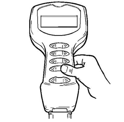
Triumph diagnostic tool
Described on the following pages is the range of information which can be retrieved from the ECM's memory and the adjustments which can be performed using the Triumph service diagnostic tool.
The tables indicate which tests are performed by the on-board system and what information can be retrieved by the Triumph diagnostic tool.
Full details of how to operate the tool and how to interpret the data follow later in this section.
Current data
By using the Triumph diagnostic tool, live engine data (engine running) can be recovered from the motorcycle. The data available is:
| Function Examined | Result Reported (Scale) |
| Engine speed | RPM |
| Calculated load | % |
| Coolant temperature | °C |
| Short term fuel trim | % |
| Throttle Position | % |
| Intake air temperature | °C |
| Vehicle speed | km/h |
| Ignition Advance | degrees |
| Heated oxygen sensor output voltage | volts |
| Intake manifold absolute pressure | mm/hg |
| Fuel system status | open or closed loop operation |
Freeze-frame data
Freeze frame data is stored at the time a DTC is recorded (confirmed) by the ECM. If multiple DTCs are recorded, the freeze-frame data which is stored will relate to the first recorded DTC only.
By calling up freeze frame data associated with the first recorded DTC, the technician can check the engine condition at the time the fault occurred. The data available is:
| Function Examined | Result Reported (Scale) |
| Engine speed | RPM |
| Calculated load | % |
| Coolant temperature | °C |
| Short term fuel trim | % |
| Throttle Position | % |
| Intake air temperature | °C |
| Vehicle speed | km/h |
| Ignition Advance | degrees |
| Heated oxygen sensor output voltage | volts |
| Intake manifold absolute pressure | mm/hg |
| Fuel system status | open or closed loop operation |
Function tests
The system allows the diagnostic tool to perform a series of function tests on various actuators in the engine management system. In some cases it is necessary to make a visual observation of a component and in other, if faults are present, DTCs will be logged.
The function tests available are:
| Function Examined | Report Method |
| Instrument panel | Visual inspection of instruments |
| Idle speed control stepper motor | Stored fault code* |
| Purge control valve | Stored fault code* |
| Fuel pump relay | Stored fault code* |
| Fuel pump operation | Stored fault codeVFuel pressure test |
| Cooling fan | Stored fault code*/fan operation |
| 2nd throttle control stepper motor | Stored fault code* |
* If a fault is detected.
Adjustments
Using the Triumph diagnostic tool, it is possible to reset the ECU to the factory default settings and to balance the throttle bodies.
Further facilities are provided to allow correct replacement/adjustment of the primary throttle position sensor and the primary throttle stepper motor. These facilities are needed as, after replacement of the parts concerned, adjustments have to be made to specific voltage settings, all with the throttles in a specific position.
Full details of these procedures are provided later in this section.
Adaption status
Because the fuel system is adaptive, the tool is able to automatically adjust to new working conditions. This screen displays information as to the adaption status of the vehicle which will show if it has adapted or not.
| Function Examined | Report Method |
| Closed throttle position reference status | adapted/not adapted |
| Idle speed control adaption status | % |
| Oxygen sensor adaption status (off idle) | % |
| Oxygen sensor adaption range (off idle) | % |
| Oxygen sensor adaption status (idle) | % |
| Oxygen sensor adaption range (idle) | % |
Build data
The following items of build data can also be read.
Function examined:
- Vehicle identification Number (VIN)
- Triumph ECM part number
- ECM manufacturer's part number
- ECM serial number
- Software version number (tune number)
Checks
When using this function it is possible to check the status of various sensors and actuators and also check certain items of factory data logged during vehicle assembly.
The data sets are dived into three groups, voltages/ pressures, throttles/coils/injectors and other data
The data available under voltages is:
| Item Checked | Result Unit |
| Throttle position sensor voltage | Volts |
| Throttle position | % open |
| Manifold absolute pressure sensor voltage | Volts |
| Manifold absolute pressure {one reading per cylinder) | mmHg |
| Atmospheric pressure sensor voltage | Volts |
| Atmospheric pressure | mmHg |
| Battery voltage | Volts |
| Battery voltage scaling | Volts |
| Coolant temperature sensor voltage | Volts |
| Air temperature sensor voltage | Volts |
| Oxygen sensor voltage | Volts |
| Oxygen sensor reading | Volts |
| 2nd throttle position sensor voltage | Volts |
| 2nd throttle position | % open |
| Gear position sensor voltage | Volts |
| Fuel level sensor voltage | Volts |
| Fall detection switch voltage | Volts |
| Fuel sensor voltage | Volts |
The data available under throttles/coils/injectors is:
| Item Checked | Result Unit |
| 2nd throttle current steps | numeric |
| 2nd throttle target steps | numeric |
| Injector 1 pulse time | milliseconds |
| Injector 2 pulse time | milliseconds |
| Injectors pulse time | milliseconds |
| Injector 4 pulse time | milliseconds |
| Ignition timing cyl 1 | degrees BTDC |
| Ignition timing cyl 2 | degrees BTDC |
| Ignition timing cyl 3 | degrees BTDC |
| Ignition timing cyl 4 | degrees BTDC |
| Coil 1 dwell time | milliseconds |
| Coil 2 dwell time | milliseconds |
| Coil 3 dwell time | milliseconds |
| Coil 4 dwell time | miiliseconds |
The data available under "other" is:
| Item Checked | Result Unit |
| Malfunction indicator light status | MIL off/on |
| Fan relay status | Fan off/on |
| Starter relay status | Starter on/off |
| Fall detection status | Normal/over |
| Oxygen sensor heater status | Heater on/off |
| Secondary air injection status | SAI on/off |
| Engine rpm | RPM |
| Vehicle speed | km/h |
| Short term fuel trim | +/-100% |
| Calculated load | % |
| Idle reference speed | RPM |
| Idle speed control target steps | numeric |
| Purge valve duty cycle | % |
| Gear position | numeric value |
| Neutral switch | Gear/neutral |
| Low fuel alarm status | On/off |