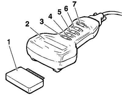
1. Memory card; 2. Screen; 3. Return key; 4. Up key; 5. Down key; 6. Validate key; 7. Help key
The memory card (1) contains all the information necessary to allow the technician to follow a number of different paths to:
- Diagnose faults
- Obtain data
- Make checks / adjustments
It is removeable to allow replacement / update cards to be inserted.
The screen comprises four horizontal lines and twenty vertical columns forming a series of boxes into which letters and numbers can be displayed to provide the necessary question, message, answer etc.
At the left of the screen, one or more symbols as detailed below may be displayed.
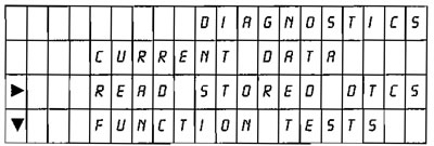
Typical screen showing symbol examples
▲▼ Cursors to indicate that further lines of text are available to be seen above and/or below those already in view, by scrolling the text up or down using the "Up" or "Down" keys.
▶ Cursor to show which line of text is "active".
? Indicates further help/guidance information available on that line by pressing the help key.
Tool keys
In most cases, the Return key (⏎) enables the user to return to the screen last displayed.
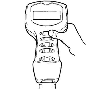
Return key
The Up and Down keys - press to move the lines of text up or down. They are also used to enter the Dealer number and the date.
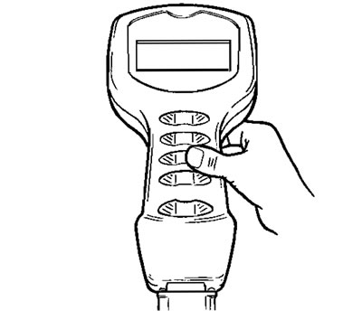
Up/down keys (2 separate keys)
Press the Validation key (*) to move on to the next message.
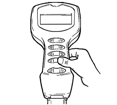
Validation key
The Help key can be used when the "?" symbol shows, to get more information about that line of text. To return to the diagnostic screen from the help area, press the help "?" button again.

Test Procedure
The following describes the procedure to follow when using the service diagnostic tool. It does not cover the further diagnosis that must be carried out once a fault area has been identified. For details of the procedure to follow when a fault area or fault code has been identified, refer to the diagnosis details later in this section.
Note:
- The tool does not retain any memory of faults, diagnosis etc. carried out on any particular motorcycle. Any such memory is only retained in the motorcycle's ECM.
- The following five pages describe the tool operations in flow chart form.

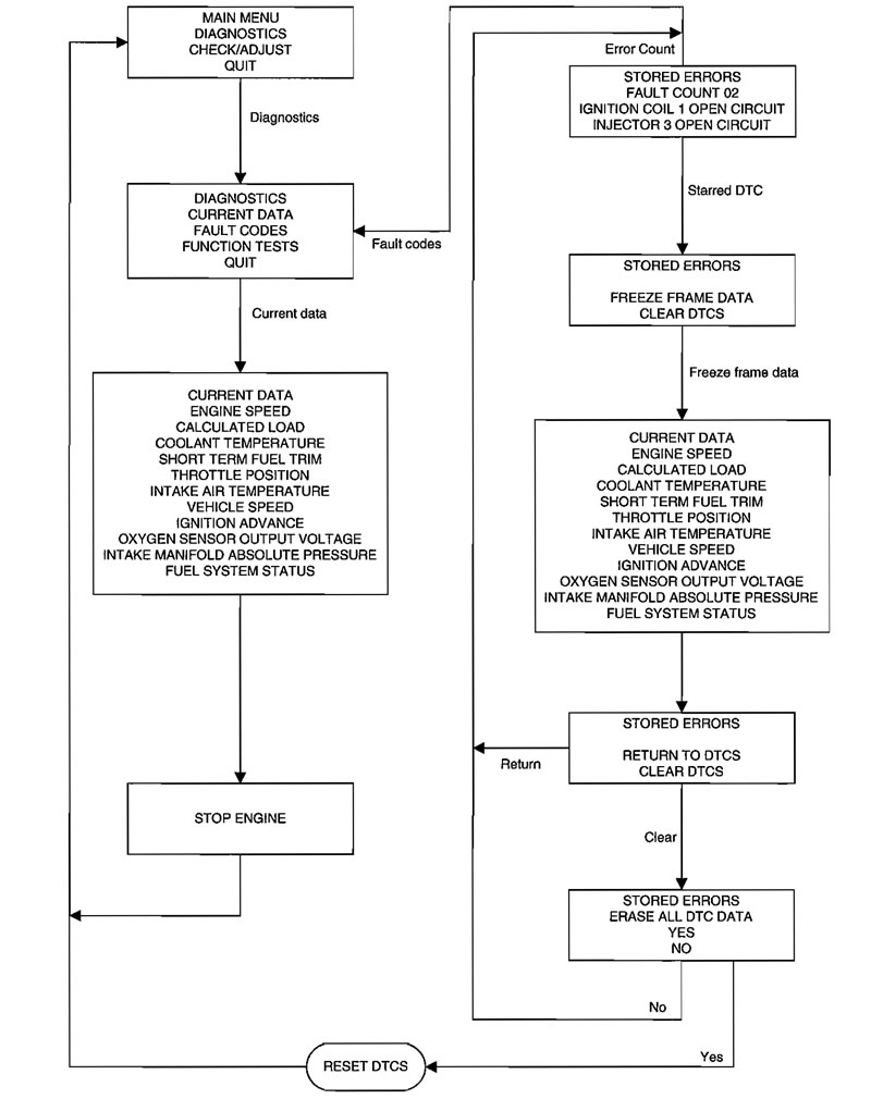
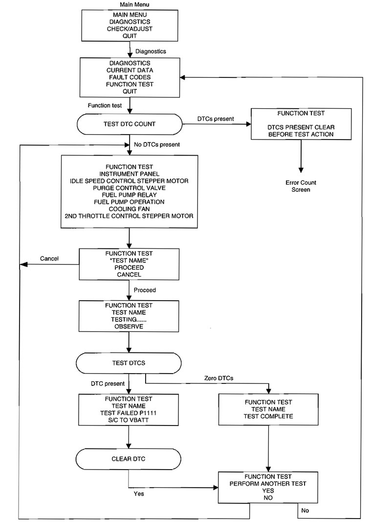


1. Connection and power-up
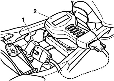
1. Tool; 2. Connection to main harness
Connect the tool to the dedicated multiplug under the seat.
A message appears on the screen and certain checks are made automatically, e.g. Is the memory card fitted?
"SELECT LANGUAGE" will then be displayed.
2. Select language
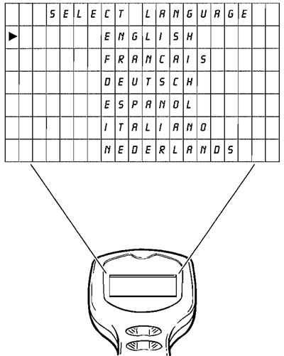
Use the "Up" and "Down" keys to move the cursor in column 1 and select the language required.
Note: The tool will always select English as the default language, and it is only necessary to use the cursor to select one of the other languages. The entire diagnostic session will then continue in the chosen language.
Press the validation key to move on.
3. Triumph motorcycles
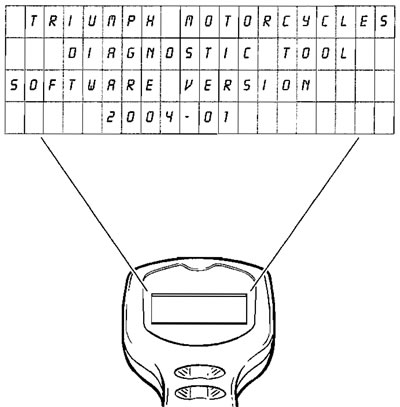
The screen will display the message "Triumph Motorcycles Diagnostic Tool" and will also give the diagnostic software version and the software release year.
Press the validation key "*" to move on.
If the Return key (⏎) is pressed, the tool will return to the "SELECT LANGUAGE" display.
4. Switch on bike ignition
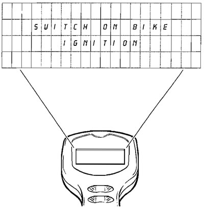
Switch on the ignition. Do NOT start the engine.
Press the validation key "*". During a short delay period the tool will carry out certain validation checks.
If it detects a problem which will invalidate the test, "DATA LINK FAULT RETRY?" will be displayed.
If all is OK, "SERVICE DATA" will appear on the screen.
5. Data link fault retry?

If the above is displayed, check that the ignition is switched on.
If the ignition is already on, the problem may be caused by bad connections, faulty ignition switch, cable break, faulty ECM, flat battery etc.
Press the Help key "?" for advice.
Rectify the problem and press the Validation key "*" to return to "SWITCH ON BIKE IGNITION".
Press the Validation key again. If the tool accepts that the problem has been rectified, "SERVICE DATA" will be displayed.
This is the first of 2 screens for which the operator has to input information, without which the testing cannot proceed further.
6. Service data - dealer
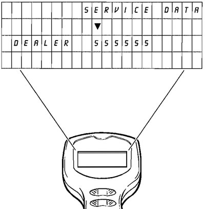
Enter your Dealer number as follows:
The number "555555" is displayed, with the cursor pointing down at the first digit.
Press the "Up" or "Down" keys to change this digit to the first digit of your dealer code.
Press the Validation key "*".
The cursor will now re-position over the second digit "5". Enter the 2nd digit of your Dealer number in the same way.
Continue until all 5 digits of your dealer code have been entered.
Note: If any digit has been entered incorrectly, press the "Return" key (⏎) to start again.
When all 5 digits have been entered correctly, press the Validation key "*".
You must enter a valid Dealer Number to continue. If you do not know your dealer number, contact Triumph or your importer for advice.
7. Service data - date
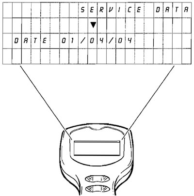
Enter the date using the "Up" and "Down" keys in the same way that the Dealer number was entered.
Note:
- 6 digits must always be entered, e.g. if it is the 7th month this must be entered as 07.
- The date must be entered in the order Day/Month/Year.
When complete, press the Validation key to display - "MAIN MENU".
8. Main menu
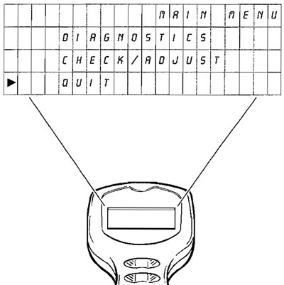
When this screen is displayed, you have to decide whether to proceed along one of two routes:
- "DIAGNOSTICS"
- "CHECK/ADJUST"
The "DIAGNOSTICS" menu provides access to:
Current data e.g. actual engine temperature, engine speed etc.
Diagnostic Trouble Codes (DTC's) i.e. access to codes stored in the motor cycle ECM which indicate a confirmed fault(s) in the system.
Function tests e.g. of tachometer, water temperature gauge, fuel pump etc.
The "CHECK/ADJUST" menu provides:
Checks i.e. build information, system data.
Adjustments e.g. adjustment of idle fuel/СО etc., and entry of software updates.
Use the "Up and Down" keys to position the cursor opposite the desired choice, and press the Validation key "*".
Either "DIAGNOSTICS" (operation 9). or "CHECK/ADJUST" (operation 27). will be displayed, dependent on the selection.
Note: If "QUIT" is selected and the validation key pressed, the display will return to "TRIUMPH MOTORCYCLES".
9. Diagnostics (If "DIAGNOSTICS" is selected)
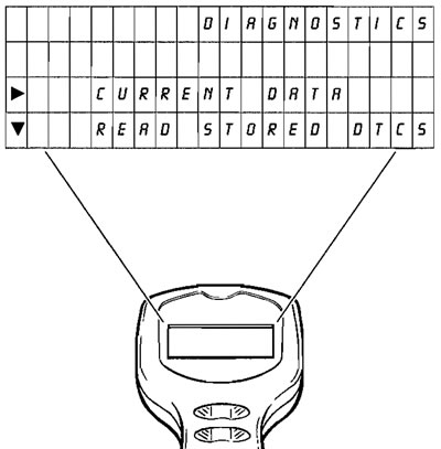
This display is the "DIAGNOSTICS" menu.
Use the "Up" and "Down" keys to scroll the text until the horizontal arrowhead is positioned opposite the desired choice, and press the Validation key "*".
The choices are:
- "CURRENT DATA" (see operation 10).
- "READ STORED DTCS" (see operation 12).
- "CLEAR DTCS" (see operation 17).
- "FUNCTION TESTS" (see operation 18).
- If "QUIT" is selected, the display will return to "TRIUMPH MOTORCYCLES".
10. Current data
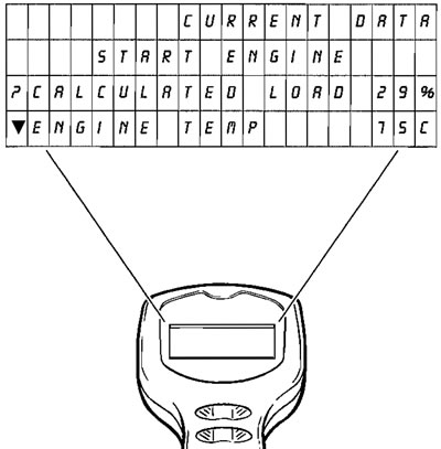
Start the engine. "CURRENT DATA" includes the information shown in the table below which can be accessed by scrolling, using the "Up" and "Down" keys. At the end of each line of text, the actual reading at that instant is provided to assist diagnosis e.g. ENGINE TEMP - 75°C.
For a complete list of the items reported, see the table titled "CURRENT DATA" earlier in this section.
If further clarification of any line of displayed text is required, scroll that line opposite the "?" symbol in the left hand column and press the Help key (?). Limited information on the selected topic will then be displayed.
Press any key to return to the "CURRENT DATA" text. When all information has been noted, press either the Validation "*" or Return (⏎) keys.
11. Stop engine

Switch off the engine.
As the tool is powered from the motorcycle, this will end the diagnostic session. To continue, return to the power-up section and select tests as required.
12. To select "READ STORED DTCS" (Diagnostic Trouble Codes) from the MAIN MENU:
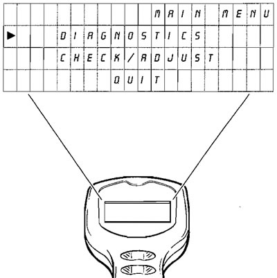
Use the "Up" and "Down" keys to position the cursor opposite DIAGNOSTICS.
Press the Validation key "*" to display "DIAGNOSTICS" menu.
Select "READ STORED DTCS", and press the Validation key "*".
"STORED DTCS" will be displayed.
13. Stored DTCS

The second line - "DTC COUNT", shows the number of DTC's stored in the ECM memory.
Lines 3 and 4 display up to two of the DTC'S stored (if any). If additional DTC'S are stored, this will be indicated by a downward pointing arrowhead, and it/ they can be accessed using the "Up" and "Down" keys.
If there are no DTC's shown, press the Return key (J) to return to MAIN MENU.
(If DTC's are present when the Return key is pressed, display will read "STORED DTCS, ERASE ALL DTC DATA YES/NO").
Information about each DTC can be obtained by scrolling the text until the appropriate code is opposite the "?" in line 3; then press the Help key (?).
- DTC example: P0117
- Help text: MAP SENSOR LOW VOLTAGE
Press the Validation key "*" to continue (operation 14).
IMPORTANT: If a DTC has an asterisk (*) to its right, this indicates that a snap shot of engine data at the time the DTC was stored is available to aid your fault diagnosis. To access this information, press the Validation key to go to operation 14. and open "FREEZE FRAME DATA".
14. Three options are now available
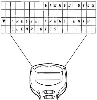
Align "FREEZE FRAME DATA" with the cursor, and press the validation key to display "FREEZE FRAME" (see 15).
Align "CLEAR DTCS" with the cursor, and press the validation key "*" to display "ERASE ALL DTC DATA" (see 17).
Press the Return key (J) to go back to "STORED DTCS" (operation 13).
15. Freeze frame
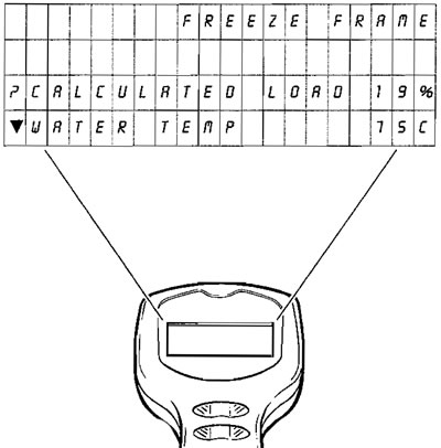
When a fault occurs which causes a DTC to be stored in the memory, the engine condition data at that instant is logged in the ECM. If another, more serious DTC is subsequently set, the original DTC data is automatically erased and new data associated with the latest DTC is logged in its place.
By selecting "FREEZE FRAME", this information becomes available on the screen to aid diagnosis. Scroll the text up or down to view the data. More information can be gained by scrolling the text line in question to line 3 (?), then press the Help key (?) as before. Press the Validation key to display "STORED DTCS" (operation 16.}.
For a complete list of the items reported, see the table titled "FREEZE FRAME DATA" earlier in this section.
16. Stored DTCS

2 options are now available:
Scroll to "RETURN TO DTCS" and press the Validate key to return to operation 13.
Scroll to "CLEAR DTCS" and press the Validation key to go on to operation 17.
Note: A full list of all the possible DTCs can be found earlier in this section.
17. Stored DTCS, erase all DTC data

Scroll to position either «YES' or 'NO' opposite the cursor.
If "YES" is selected, press the Validation key to erase all DTC data from the memory. "MAIN MENU" will then be displayed.
Note: If you intend to examine the Function Tests, entry will be inhibited unless the DTC's have been erased.
If "NO" is selected, press the Validation key "*" to return to operation 13.
That completes the DTC cycle.
18. To select "FUNCTION TESTS" from the MAIN MENU:
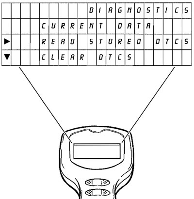
Use "Up" and "Down" keys to select "DIAGNOSTICS" menu.
The following choices are available.
Press the Validation key "DIAGNOSTICS" will be displayed.
Select "FUNCTION TESTS", and press the Validation key
If no DTCS are stored, "FUNCTION TEST" will be displayed (see operation 20).
If one or more DTCS are stored, the message "DTCS PRESENT CLEAR BEFORE TEST ACTION" will be displayed (see operation 19).
Note: The diagnostic tool will not allow Function Tests to be accessed until all DTC's in the memory are removed.
19. Function tests

To clear the DTC's, press the Validation key "*". "STORED DTCS" will be displayed (see operation 13).
Proceed as before via operations 14 to 17. Scroll to "YES" and press the Validation key "*" to erase all DTC data; the MAIN MENU will be displayed again.
Note:
- The fault(s) which caused the DTC's to be set must be rectified and cleared before continuing the Function Tests.
- A full list of all the possible DTCs can be found earlier in this section.
Select "DIAGNOSTICS" menu and "FUNCTION TESTS" again pressing the Validation key "*" each time.
Because the DTC's have now been erased, "FUNCTION TEST" (operation 20) will now be displayed.
20. Function test
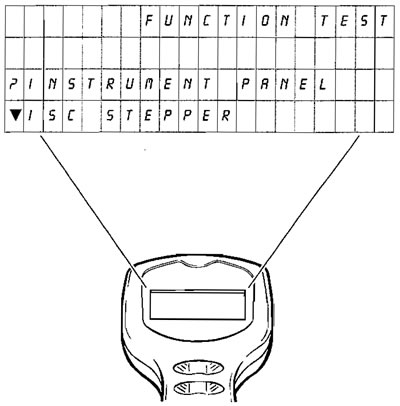
The following can be tested:
- a) Instrument panel.
- b) Idle speed control stepper.
- c) Purge valve.
- d) Fuel pump prime.
- e) Cooling fan operation.
- f) Fuel pump operation.
- g) Second throttle control stepper motor.
If the fault is electrical, this will then be reported as a DTC.
Instrument Panel test: A signal is sent which should cause the tachometer to read approximately 7,500 RPM, the water temperature gauge to show 100°C* and the speedometer 100 km/h*, all for 10 seconds.
idle speed control stepper: A signal is sent which should cause the stepper to be driven to the fully closed position, then to the fully open position, pausing briefly in each position. DTCs are set if a malfunction is found.
* Or the imperial equivalents.
Purge valve (California models only): This test allows you to check operation of the valve. To detect valve operation, use a stethoscope to listen for valve operation. DTCs are set if a malfunction is found.
Fuel pump prime: This test provides you with the means to physically check the pump and relay operation. DTCs are set if a malfunction is found.
Cooling fan test: A signal is sent which should cause the fan to operate for a 10 second period. DTCs are set if a malfunction is found.
Fuel pump operation: This test provides you with the means to physically check the pump operation. DTCs are set if a malfunction is found. The pump is energised when the test is confirmed and ended when the Validation key is pressed for a second time.
Second throttle stepper motor: A signal is sent which should cause the 2nd throttle stepper to be driven to the fully closed position, then to fully open. DTCs are set if a malfunction is found.
By pressing the Validation key your selection will be noted and "FUNCTION TEST" (operation 21). will be displayed.
Press the Help key (?) for more information.
Note: If the Return key (J) is pressed, the tool will return to "DIAGNOSTICS" menu (operation 9).
21. Function test
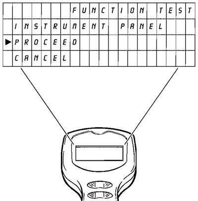
The function selected at operation 20. will now show on line 2. To show an example of this, we have chosen the "INSTRUMENT PANEL" test.
If you press the Help key (?). help relating to the specific test will be given. In this example, the screen will now read
- TACHOMETER - 7500 RPM
- TEMP GAUGE - not fitted, test will illuminate High Temp warning light.
- SPEEDOMETER - 100 km/h*
* Or the imperial equivalents.
If you wish to cancel that selection, scroll to "CANCEL" and press the Validation key The display will return to operation 20.
If you wish to test the component selected, scroll to "PROCEED" and press the Validation key
22. Function test
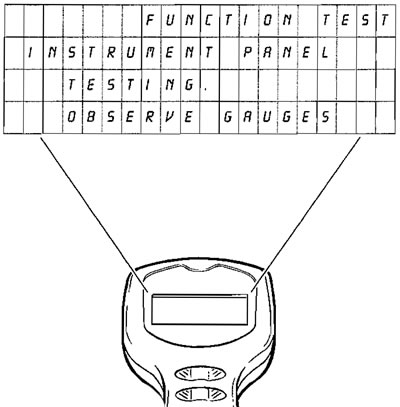
The screen now displayed will be specific to the component being tested;
In the example selected - "INSTRUMENT PANEL", the instruction is to observe the gauges.
After a period of time, the screen will automatically change to either "TEST COMPLETE" (see operation 23). which will indicate a satisfactory completion, or to "TEST FAILED" (see operation 25). which will indicate failure.
23. Function test
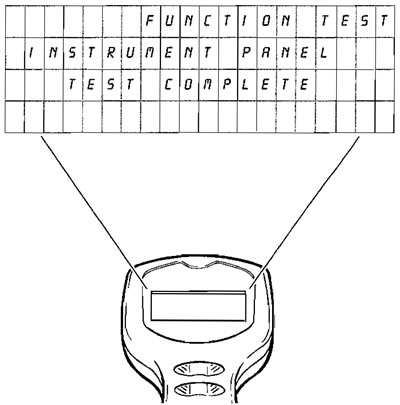
If the test is satisfactory the display will read "TEST COMPLETE". Press the Validation key "*" to display "FUNCTION TEST" (operation 24).
24. Function test

This display allows you to decide whether you wish to test another component.
Either - position the cursor on line 3 "YES" and press the Validation key '*' to return to the "FUNCTION TEST" selection menu, or - position the cursor on line 4 "NO" and press the Validation key to return to "DIAGNOSTICS" menu (operation 9).
25. Function test

If the test selected at operation 22 is unsatisfactory, a DTC will be displayed on line 3 of this display.
Press the Help key (?) to access the diagnosis information associated with that code.
Press the Validation key if you wish to test another component (operation 24).
Note: Any DTCs logged in the system will be automatically cleared at this point.
To return to the "DIAGNOSTICS" menu, Select "QUIT" and press the Validation key "*" to return to the "MAIN MENU" (operation 8).
That completes the "FUNCTION TESTS" cycle.
26. To select "CHECKS/ADJUSTMENTS" from the MAIN MENU (operation 6).:
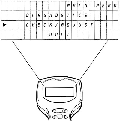
Use the "Up" and "Down" keys to position the cursor opposite "CHECK/ADJUST".
Press the Validation key the "CHECK/ADJUST" menu wiil be displayed.
27. Check/adjust
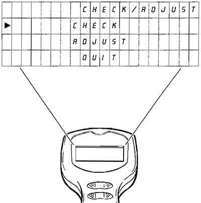
Use the "Up" and "Down" keys to position the cursor as follows, and then press the Validation key
Opposite "CHECK" - "CHECKS" will be displayed (operation 28).
Opposite "ADJUST" - "ADJUST" will be displayed (operation 32).
Opposite "QUIT" - to return to "MAIN MENU" (operation 8).
28. Checks
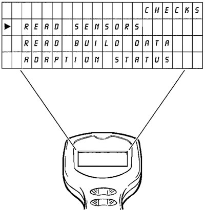
You now have the option to access the motorcycle "BUILD DATA" or the "SYSTEM DATA", or to quit.
Position the cursor as follows and then press the Validation key "*":
Opposite "READ SENSORS" - "SENSOR DATA" (operation 30) will be displayed.
Opposite "READ BUILD DATA" - "BUILD DATA" (operation 29) will be displayed.
Opposite "ADAPTION STATUS" - "ADAPTION DATA" (operation 31) will be displayed if the coolant temperature is higher than 90°C. If not, a holding screen will be displayed indicating the current temperature.
Opposite "QUIT" - to return to "MAIN MENU" (operation 8).
29. Build data

Providing the information was recorded at the time of build, the display will show the following information relating to the motorcycle under test by scrolling up and down. Before displaying the recorded information, the tool will briefly display the message, "PLEASE WAIT, CHECKING BUILD DATA".
- Vehicle Identification Number (VIN)
- Triumph ECM part number
- Manufacturer's ECM part number
- ECM Serial number
- Tune Number
Press the Validation "*" keys to return to "CHECK/ ADJUST" menu (operation 27).
30. Sensor data
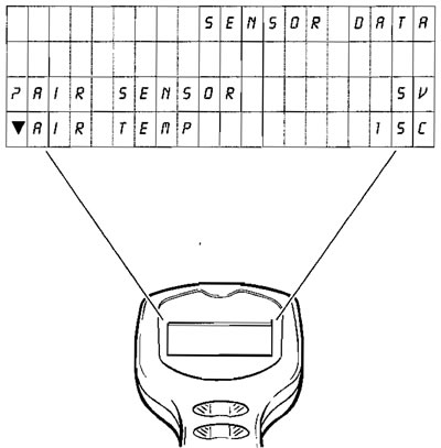
The display can be scrolled to show:
The status of the various sensors and actuators
To obtain further data information, scroll the appropriate line to the help key mark (?) and press the Help key.
Note: The help information shows the likely range of readings for a correctly functioning system at normal operating temperature.
That completes examination of the Checks.
Press the Validation key to return to "CHECK/ADJUST" (operation 27).
31. Adaption status
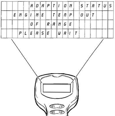
Because adaption only takes place at normal operating temperature, the above screen will be displayed until the engine reaches normal operating temperature.
Until the engine warms or cools to the correct temperature range, the tool will not allow access to any other functions. If you wish to escape from this area (and not carry out the adjustment) switch off the ignition and disconnect the tool.
Once the correct temperature range has been reached, the "ADAPTION STATUS" screen (operation 32). will automatically be displayed.
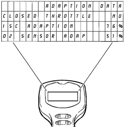
The display can be scrolled to show:
The adaption status of the various sensors and actuators involved in the adaption process will give an indication as to whether or not the vehicle is correctly adapted. If the readings show an incorrect adaption status, refer to the table of contents for the location of further information and the actions necessary to force correct adaption.
See page 8-110 for additional information on forcing adaption.
The data displayed under this option are:
| Function Examined | Report Method |
| Closed throttle position reference status | adapted/not adapted |
| Idle speed control adaption status | % |
| Oxygen sensor adaption status (off idle) | % |
| Oxygen sensor adaption range (off idle) | % |
| Oxygen sensor adaption status (idle) | % |
| Oxygen sensor adaption range (idle) | % |
Note: Several forced adaptions may be needed to fully adapt an individual motorcycle.
32. Adjust
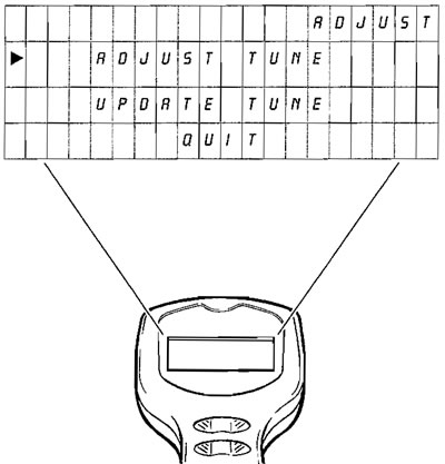
Position the cursor on line 2 "ADJUST TUNE" if you wish to check and/or adjust the values of certain tune items. Then press the Validation key to display "ADJUST TUNE" (see operation 33).
In special circumstances, Triumph will request you to introduce a completely new engine tune. Given this situation, select "UPDATE TUNE" and press the Validation key (see operation 36).
33. Adjust tune
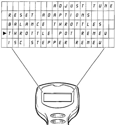
The following allow adjustments to be made to items which affect the engine operation
Position the cursor opposite the setting you wish to adjust and press the Validation key "*".
RESET ADAPTIONS. - See operation 34.
BALANCE THROTTLES. - See operation 35.
THROTTLE POT RENEW. - See page 8-102 for details on when and how to use this function.
IDLE SPEED CONTROL STEPPER RENEW - See page 8-106 for details on when and how to use this function.
34. Adjust tune (adaption reset)
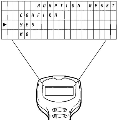
After selecting the adaption reset option, confirm or reject the option by positioning the cursor opposite the option chosen and press the Validation key "*".
If YES is chosen, a screen will confirm that adaptions have been reset.
If NO is chosen, you will be returned to the adjust tune menu.
Note: Resetting the adaption values does not adapt the motorcycle. This can only be done by the method explained later in this section. Adaption reset only returns adaption values to their "start" point.
35. Balance throttles
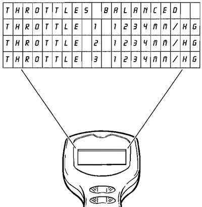
Using the BALANCE THROTTLES command, the throttles may be balanced without the need to connect an external device to measure the vacuum levels in each throttle body. The diagnostic tool displays data taken from the manifold absolute pressure sensor reading for each throttle.
Once throttle imbalance has been reduced to a predetermined level, the top line of information will display the word "BALANCED". Under any other conditions where imbalance is detected, nothing will be displayed indicating that the throttles require balancing.
36. Update tune
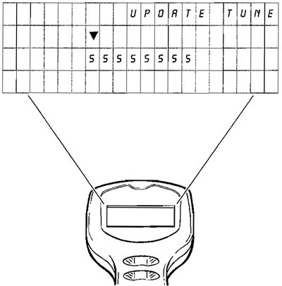
(Accessed from operation 32). On receipt of special instructions from Triumph you may be asked to input a completely new engine tune.
To do this, they will give you a password number which must be entered using the "Up" and "Down" keys in the same way as was done to enter your dealer code number.
After entering the final digit, press the Validation key "*" again.
If the password number entered is invalid, the screen shown in operation 36 will be displayed.
If the password number is valid, the tool will briefly display the message, "PLEASE WAIT, CHECKING ECM TYPE" then, "UPDATE TUNE" (operation 37). will be displayed.
37. Update tune
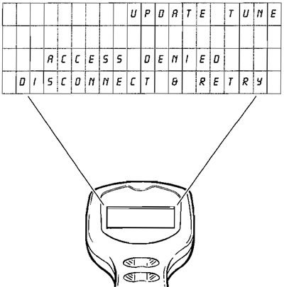
If the Password number has been incorrectly entered, the screen will display "ACCESS DENIED". Press the Validation key "*" to return to MAIN MENU (operation 8). and start again.
If after a second attempt the entry is still invalid, the screen will display "ACCESS DENIED DISCONNECT AND RETRY". The diagnostic tool must be disconnected and the complete procedure re-started.
38. Update tune
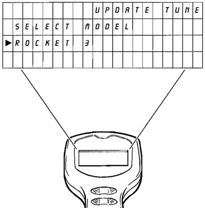
Align the cursor with the model to which a tune is to be downloaded and, when satisfied that the selection is correct, press the validation key "*".
Once a model has been selected and the validation key pressed, screen 38 will be displayed.
39. Update tune
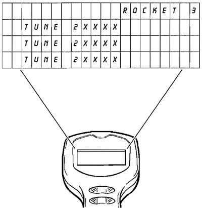
Scroll to the tune required and press the Validation key "*" to move on to operation 39.
Press the help key for information on the applicability of each tune number.
40. Update tune

Scroll to either "CONFIRM", "CANCEL" or "QUIT" (quit option will not be visible until the text has been scrolled) then press the Validation key "*".
If "QUIT" has been selected - this will return to MAIN MENU (operation 8).
If "CANCEL" has been selected - return to operation 38.
If "CONFIRM" has been selected, downloading will begin.
41. Update tune (confirm selected)
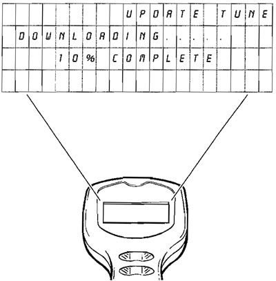
The screen will show "DOWNLOADING", and the selected software will be automatically downloaded into the ECM.
When complete, the screen will display "DOWNLOAD COMPLETE".
Press the Validation key "*" to return to the "MAIN MENU" (operation 8).
If downloading has been unsuccessful the screen will display "DOWNLOAD FAILED". Should this message appear, refer to 41, restarting tune download.
Press the Validation key to return to the "MAIN MENU" (operation 8).
Note: A TUNE DOWNLOAD CAN TAKE UP TO 15 MINUTES TO COMPLETE.
42. Restarting tune download
Caution!
- If, for any reason downloading is interrupted, the ECM will not function and tune download cannot be restarted in the normal way. This is because the tool's operating system has been erased from the ECM's memory and has not yet been fully replaced. Download interruption can occur for a variety of reasons such as, accidental disconnection of the tool, a flat battery, turning the ignition switch to OFF during download etc.
- In these circumstances, a special-tool key-presssequence must be followed which is described below.
To restart download, switch the motorcycle ignition to OFF and disconnect the tool. Reconnect the tool, switch the motorcycle ignition to ON, and scroll through to the screen shown below.

From this screen, use the following button press sequence:
HELP (?) - HELP (?) - RETURN (⏎) - HELP (?) - VALIDATE (*).
The dealer log-in screen will then be displayed. From that screen, download can be restarted in the normal way.
Note: The software version number is not relevant to this procedure. All versions of the diagnostic software will operate in the way described.
