
Removal
1. Mark each liner to identify correct orientation and the cylinder number from which it has been removed.
2. Turn the crankshaft until the piston in the liner to be removed is at the bottom of its stroke.
3. Check that the locking nut on tool T3880061 is loose, then fully unscrew the extraction nut.
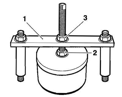
1. Tool T3880061; 2. Locking nut; 3. Extraction nut
Caution! The cylinder liners and pistons are made of aluminium alloy and can therefore be easily damaged. Handle the cylinder liner and piston with care, ensuring the internal bore of the liner and the piston skirt are not scratched.
4. Carefully fit the rubber section of the tool fully into the cylinder liner, positioning studss supplied with the tool diagonally across a pair of head boit-holes.
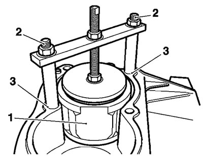
1. Cylinder liner; 2. Studs; 3. Head-bolt holes
5. Fully engage the bolt threads in the head bolt holes. It is not necessary to fully tighten the bolts.
6. Turn the locking nut clockwise until the rubber sleeve on the tool tightly grips the bore of the liner.
7. Turn the extraction nut clockwise sufficient to raise the liner and break the seal between the liner and crankcase.
Note: It is not necessary (or possible) to fully extract the liner using this tool. Once the seal is broken, the tool must be removed and the liner extracted by hand.
8. Turn the locking nut anticlockwise to release the liner.
9. Once the seal on the liner is released, remove the tool and manually remove the liner.
Installation
1. Thoroughly clean the liner removing all traces of old silicone sealer.
2, Remove all traces of sealer from the crankcase bores.
3. Apply a thin bead of silicone sealer to the liner to crankcase mating face.

1. Liner; 2. Sealer area
4. Apply a thin bead of silicone sealer to the liner to crankcase mating face.

1. Liner; 2. Sealer area
5, Carefully fit each liner over the piston using a gentle rocking motion to allow compression of the piston rings.
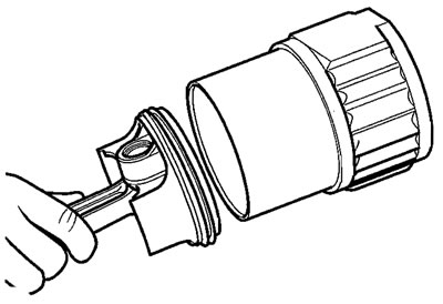
Fitting a piston into a liner
Caution! Care must be taken when installing liners such that the silicone sealer is not forced out, blocking passageways in the crankcase.
Note: The liners have a large chamfer at the bottom of the bore, enabling fitting of the piston without need for a piston ring compressor.
Caution! Fit each liner over whichever piston is at TDC. When turning the engine, do not allow the pistons to contact the inside of the crankcase and also do not allow fitted liners to lift off the crankcase base.
6. Continue fitting each liner in turn until all are fitted and sealed.
Note: When the liners have been fitted, they should not be disturbed. If it is necessary to remove the liner after fitting, the sealer must be re-applied.