
Removal
Warning! Before starting work, ensure the motorcycle is stabilised and adequately supported. This will help prevent it from falling and causing injury to the operator or damage to the motorcycle.
1. Remove the engine as described on page 10.2.
2. Separate the crankcase halves as described on page 5.5.
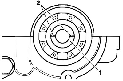
3. With the crankcase halves separated, lift out the balancer shaft complete with the bearings.

1. Balancer; 2. Crankshaft
4. If necessary, slide off the ball bearing at the end opposite to the drive gear.

1. Balancer; 2. Bearing
Note: The bearing at the gear end can only be removed in a press.
Inspection
1. Inspect all gears for chipped or missing teeth and for overheating (blue discolouration).
2. Inspect all bearings for signs of overheating (blue discolouration), seizure and any other damage. Check that all bearings rotate smoothly and without tight spots.
Assembly/lnstallation
Note: Balancer shafts and crankshafts are graded, if the balancer shaft is replaced, it must be grade-matched with the crankshaft. For identification, both are marked adjacent to the alignment dots (see note below) either "A" or "B". Always match an "A" grade crankshaft with an "A" grade balancer shaft and vice-versa.
Note: A "B" grade component does not indicate inferior quality to an "A" grade coponent.
Note: To ensure a correct relationship, the balancer must be installed in a specific orientation relative to the crankshaft. There are dot marks, one on the balancer drive gear (on the crankshaft) and one on the balancer driven gear, which must be in alignment when the balancer shaft is fitted.

1. Balancer drive gear; 2. Balancer driven gear; 3. Dot marks
Note: A further alignment check can be made if required. When number one cylinder in the engine is on top-dead-centre (TDC), slots on the end of the balancer will align with the split line of the crankcase. This allows a balancer installation check on an installed engine by removing only the clutch cover.
1. Balancer shaft; 2. Slot marks
1. Position the balancer to the upper crankcase aligning the dot marks as shown below.
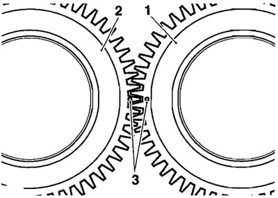
1. Balancer drive gear; 2. Balancer driven gear; 3. Dot marks
2. Position the balancer bearings such that the dowel pegs locate in slots in the upper crankcase.

1. Bearing dowels; 2. Upper crankcase slots
3. Ensure the circlips fitted to the balancer bearings locate and seat correctly in corresponding grooves, also in the upper crankcase.
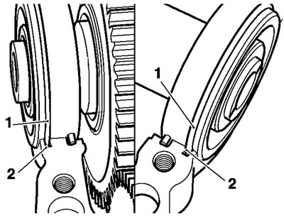
1. Circlips; 2. Grooves
4. Check that the balancer and crank dot marks are still in alignment.
5. Assemble the crankcase halves as described on page 5.7.
6. Refit the engine to the frame as described on page 10.5.