Prepare
1. Remove negative battery cable. See Power disconnect.
2. Remove alternator cover. See Alternator cover.
3. Remove alternator. See Removing and installing alternator.
4. Remove clutch cover. See Clutch cover.
Remove
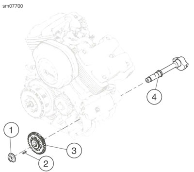
1. See Figure 4-38. Remove balancer shaft.
- a. Remove nut (1).
- b. Remove gear assembly (3).
- c. Remove key (2), if necessary.
- d. Remove balancer shaft (4).
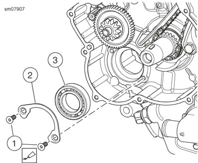
2. See Figure 4-39. Remove bearing.
- a. Remove screws (1).
- b. Remove retainer (2).
- c. Remove bearing (3).
Install
| PART NUMBER | TOOL NAME |
| HD-51441 | COUNTERBALANCER PIN |
| HD-51461 | SPRING GEAR ROTATION TOOL |
| FASTENER | TORQUE VALUE | |
| Balancer bearing retainer screws | 10.0-12.0 Nm | 89-106 in·lbs |
| Balancer shaft nut | 160.0-170.0 Nm | 118-126 ft·lbs |
1. See Figure 4-39. Install bearing.
- a. Install bearing (3).
- b. Install retainer (2).
- c. Apply LOCTITE 243 MEDIUM STRENGTH THREADLOCKER AND SEALANT (blue) to screws (1).
- d. Install screws (1). Tighten to 10.0-12.0 Nm (89-106 in·lbs).
2. See Figure 4-38. Install balancer shaft.
- a. Install balancer shaft (4).
- b. Install key (2), if previously removed.
3. See Figure 4-38. Install balancer Gear.
- a. Place gear assembly (3) on balancer shaft (4).
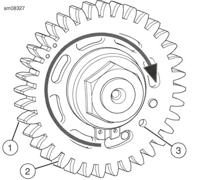
- b. See Figure 4.40. Using SPRING GEAR ROTATION TOOL (Part No. HD-51461), rotate outer gear (2) clockwise until alignment hole (3) aligns with inner gear (1) alignment hole.
- c. Insert COUNTERBALANCER PIN (Part No. HD-51441) into alignment hole (3).
- d. See Figure 4.38. Install nut (1). Tighten to 160.0-170.0 Nm (118-126 ft·lbs).

Figure 4-38. Balancer Shaft: 1. Nut 2. Key 3. Gear assembly 4. Balancer shaft

Figure 4-39. Balancer Bearing: 1. Screw (2) 2. Retainer 3. Bearing

Figure 4-40. Balancer Gear: 1. Inner gear 2. Outer gear 3. Alignment hole
Complete
1. Install alternator. See Removing and installing alternator.
2. Install alternator cover. See Alternator cover.
3. Install clutch cover. See Clutch cover.
4. Install negative battery cable. See Power disconnect.
