
Warning!
- Make sure the motorcycle is stabilised and adequately supported.
- A correctly supported motorcycle will help prevent it from falling.
- An unstable motorcycle may fall, causing injury to the operator or damage to the motorcycle.
Perform the following operations:
- Seat - removal
- Battery - removal
- Exhaust silencer - removal
- Drag and drop links - removal
- Rear suspension unit - removal
- Gear change linkage - removal
1. Release the fixings and remove the left hand control plate assembly.

1. Control plate assembly; 2. Fixings
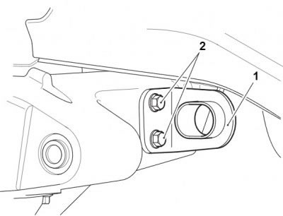
2. Release the fixings and remove the right hand heel guard. Temporarily refit the lower fixing to support the rear brake master cylinder.

1. Heel guard; 2. Upper fixing; 3. Lower fixing
Note: Note the routing of the rear brake switch harness for installation.
3. Detach the rear brake switch harness from the clip on the rear master cylinder brake hose and disconnect its multiplug.
Warning! Do not allow the rear master cylinder to hang on the brake hose as this may damage the hose. Damaged hoses could cause brake failure leading to loss of motorcycle control and an accident.
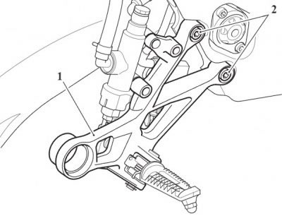
4. Remove the rear master cylinder fixings.

1. Master cylinder; 2. Upper fixing; 3. Lower fixing
5. Remove the brake pedal pivot bolt. Discard the bolt.
Note: Note the position and orientation of the clevis pin and clip for installation. Note the position and orientation of the brake switch and brake pedal return springs for installation.
6. Remove the clip and clevis pin and detach the rear brake pedal from the master cylinder push rod. Tie the rear master cylinder aside.
7. Detach the springs from the rear brake pedal and remove the pedal.
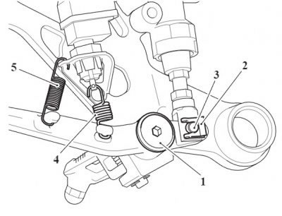
1. Brake pedal pivot bolt; 2. Clip; 3. Clevis pin; 4. Brake switch spring; 5. Brake pedal return spring
8. Release the fixings and remove the right hand control plate and brake switch assembly.
1. Control plate assembly; 2. Fixings
9. Remove the flanged sleeves and rubber grommets from exhaust silencer mounting bracket.
10. Release the fixings and remove the exhaust silencer mounting bracket.
1. Bracket; 2. Fixings
11. Set the drive chain adjustment to allow maximum free play in the drive chain (see Final drive chain Free-Movement Adjustment).
Note: The drag link frame bearings cannot be removed undamaged. Protect both sides of the frame from damage during bearing removal by applying a suitable masking tape to the area shown below.

1. Frame masking area (left hand side shown)
12. Remove the drag link bearing sleeve and seals. Discard the seals.
13. Using a suitable proprietary slide hammer bearing extraction tool, remove the drag link needle roller bearings from the frame.

1. Bearing sleeve; 2. Seals; 3. Needle roller bearings