
Warning!
- Make sure the motorcycle is stabilised and adequately supported.
- A correctly supported motorcycle will help prevent it from falling.
- An unstable motorcycle may fall, causing injury to the operator or damage to the motorcycle.
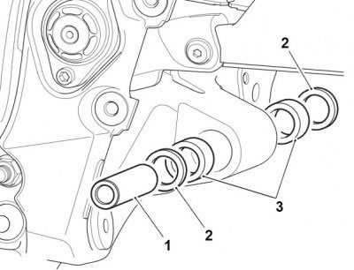
1. Bearing sleeve; 2. Seals; 3. Needle roller bearings
Note:
- Use Castrol High Temperature grease in the frame bore to aid the installation of the drag link bearings.
- A thin smear of multi-purpose NLGI 2 specification grease should be added to the bearing sleeve and seals.
- Service tool T3880368 - Bearing Installer is required to install the new bearings to the correct depth.
- Bearings are inserted by means of a draw bolt acting on the insertion tool. A support tool is located on the opposite side of the frame to the insertion tool and as the bolt is tightened, the bearing is drawn in to the frame.
- Insert bearings with the marked or shielded side facing outwards and always fit new bearing seals.
- Ensure that the frame bore is clean and free of debris before installing new bearings.
1. Using the threaded rod and nuts provided with T3880053 - Wheel Bearing Extraction Kit, assemble a new bearing (marked side facing outwards) and the insertion collars from T3880368 - Bearing Installer to the frame bore as shown below.
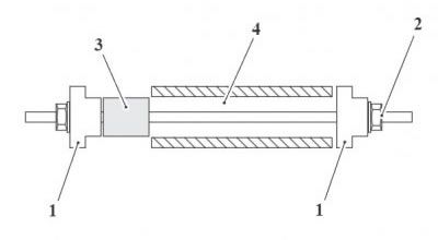
1. T3880368 - Bearing Installer; 2. Threaded rod and nut from T3880053 - Wheel Bearing Extraction Kit; 3. Bearing; 4. Frame bore
2. Ensuring that the bearing is inserted squarely, progressively tighten the nut on T3880053 - Wheel Bearing Extraction Kit until the bearing is fully inserted.
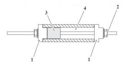
1. T3880368 - Bearing Installer; 2. Threaded rod and nut from T3880053 - Wheel Bearing Extraction Kit; 3. Bearing; 4. Frame bore
3. Repeat steps 1 and 2 for the other side.
4. Fit new bearing seals and carefully insert the bearing sleeve.
5. Set the drive chain adjustment (see Final drive chain Free-Movement Adjustment).
6. Fit the exhaust silencer mounting bracket to the frame. Tighten the fixings to 8 Nm.
1. Bracket; 2. Fixings
7. Refit the grommets and flanged sleeves to the exhaust silencer mounting bracket.
8. Fit the right hand control plate assembly. Tighten the fixings to 24 Nm.
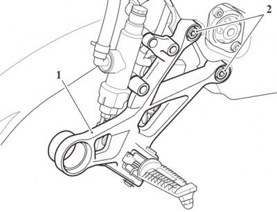
1. Control plate assembly; 2. Fixings
9. Align the rear brake pedal to the master cylinder push rod and secure with the clevis pin and clip as noted during removal.
10. Secure the brake pedal to the control plate with a new pivot bolt and tighten to 22 Nm.
11. Attach the brake switch and pedal return springs to the rear brake pedal as noted during removal.

1. Brake pedal pivot bolt; 2. Clip; 3. Clevis pin; 4. Brake switch spring; 5. Brake pedal return spring
12. Route the rear brake switch harness as noted during removal and connect the multiplug. Secure the harness into its clip on the rear master cylinder brake hose.
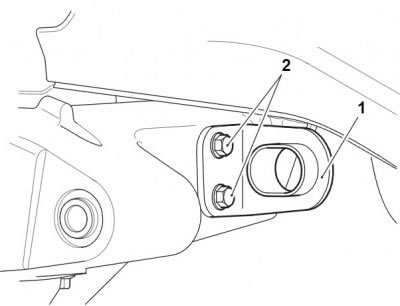
13. Secure the master cylinder to the control plate as follows.
- Temporarily fit the lower M8 x 35mm fixing. Do not fully tighten.
- Fit the upper M8 x 25 mm fixing. Tighten to 16 Nm.
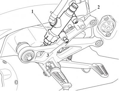
1. Master cylinder; 2. Upper fixing; 3. Lower fixing
14. Remove the lower M8x35 mm fixing.
15. Secure the heel guard to the control plate as follows:
- Fit the lower M8x35 mm fixing through the heel guard, control plate and master cylinder.
- Fit the upper M8x20 mm fixing.
- Tighten both fixings to 16 Nm.
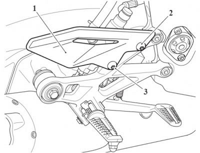
1. Heel guard; 2. Upper fixing; 3. Lower fixing
16. Refit the left hand control plate assembly. Tighten the fixings to 24 Nm.
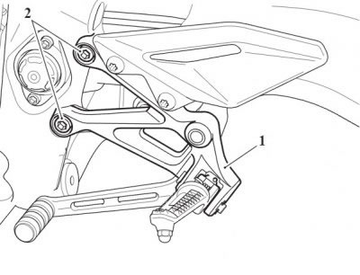
1. Control plate assembly; 2. Fixings
Perform the following operations:
- Gear change linkage - installation
- Rear suspension unit - installation
- Drag and drop links - installation
- Exhaust silencer - installation
- Battery - installation
- Seat - installation
Warning!
- Make sure the motorcycle is stabilised and adequately supported.
- A correctly supported motorcycle will help prevent it from falling.
- An unstable motorcycle may fall, causing injury to the operator or damage to the motorcycle.
Perform the following operations:
Warning! When using a press, always wear overalls, eye, face and hand protection. Objects such as bearings frequently break-up under load and the debris caused during break-up may cause damage and injury to unprotected parts of the body. Never wear loose clothing, which could become trapped in the press and cause crushing injury to the hand, arms or other parts of the anatomy.
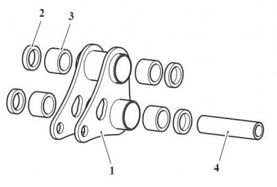
1. Drop link; 2. Seals; 3. Needle roller bearings; 4. Bearing sleeve (drag link mounting)
Removal
1. Remove the drop link bearing sleeves and seals. Discard the seals.
2. Using a suitable press, remove the needle roller bearings.
Installation
Note:
- The drop link bearings are 'dry fit' bearings and grease or other forms of lubrication should not be used during installation. However, a thin smear of multi-purpose NLGI 2 specification grease should be added to the bearing sleeve and seals.
- Service tool T3880368 - Bearing Installer is required to install the new bearings to the correct depth.
- Insert bearings with the marked or shielded side facing outwards and always fit new bearing seals.
- Ensure that the bearing bore is clean and free of debris before installing new bearings.
1. Install the new bearings (marked side facing outwards) to the correct depth using T3880368 - Bearing Installer and a suitable press.
2. Fit new bearing seals and carefully insert the bearing sleeves.
Perform the following operations: