
Caution!
- The fixings for the throttle position sensor, throttle butterfly adjustment screws and the throttle hard stop blanking screw are marked with yellow paint and must not be loosened or removed.
- If the fixings, adjustment screws or blanking screw have been loosened or removed the throttle body assembly must be replaced as there are no means to reset these items to their correct positions.
Note:
- The fixings for the throttle position sensor, throttle butterfly adjustment screws and the throttle hard stop blanking screw are marked with yellow paint and must not be loosened or removed. If the fixings, adjustment screws or blanking screw have been loosened or removed any warranty claims for the throttle bodies will be rejected.
- The three air bypass adjustment screws on the throttle bodies also have the yellow paint on them, these three screws can be moved for throttle balance only.
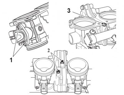
1. Throttle position sensor fixings; 2. Throttle butterfly adjustment screws; 3. Throttle hard stop blanking screw
The throttle body balance adjustment is made with the air bypass adjustment screws only. This adjustment alters the amount of air that can flow through the air bypass drilling.
Note: DO NOT remove the throttle hard stop blanking screw to adjust the throttle balance.
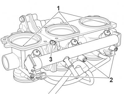
1. Air bypass drilling (throttle bodies shown removed for clarity); 2. Air bypass adjustment screws; 3. Throttle hard stop blanking screw
Adjust the air bypass screws such that there is a minimum amount of adjustment used on each adjustment screw to achieve throttle balance. For example, if MAP pressures were as follows and were shown to be out of balance:
- Cylinder 1 MAP Pressure: 490 mmHg
- Cylinder 2 MAP Pressure: 435 mmHg
- Cylinder 3 MAP Pressure: 415 mmHg
Each cylinder should be adjusted to 450 mmHg, this will help minimise the amount of adjustment at each adjustment screw.
Note: The throttles cannot be balanced using equipment to measure vacuum in each throttle. Instead, the Triumph diagnostic software must be used.
Warning! If the engine has recently been running, the components beneath the fuel tank may be hot to the touch.
Warning!
- Make sure the motorcycle is stabilised and adequately supported.
- A correctly supported motorcycle will help prevent it from falling.
- An unstable motorcycle may fall, causing injury to the operator or damage to the motorcycle.
Perform the following operations:
1. Turn the ignition to the OFF position.
Warning! Always use the correct fuel pressure gauge adapter (adapter 'B'). Use of an incorrect adapter will result in a fuel leak. A fuel leak can result in a fire causing damage to property and injury to persons.
1. Using T3880123 - Extension Cable carefully connect the fuel pump connection on the extension harness to the fuel tank. Connect the other end of the harness extension to the motorcycle main harness.
2. Select the fuel pressure gauge adaptor marked B from T3880001 - Fuel Pressure Gauge.
3. Connect the adaptor hose to the fuel pump plate outlet as shown in the illustration below.

1. Adaptor hose B; 2. Fuel pump plate outlet; 3. T3880123 - Extension Cable
4. Connect the fuel hose to the adaptor hose.
Note: If disconnected, temporarily reconnect the immobiliser multiplug.
5. Attach exhaust extraction hoses to the silencer.
6. Attach the Triumph diagnostic tool to the dedicated plug, refer to the Triumph Diagnostic Tool User Guide. Start the engine, and allow to idle.
7. On the diagnostic software navigate to ADJUST TUNE.
8. Select BALANCE THROTTLES.
9. Click the Adjust button.
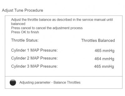
Balance throttles screen
Note:
- The balance throttles screen will show the vacuum value of each throttle in mmHg. In addition, when the throttles are balanced to an acceptable range of each other the words THROTTLES BALANCED in green text will appear on the right of the screen. At this point, no further adjustment is necessary or productive.
- If the throttles are not balanced to each other the word THROTTLES UNBALANCED in red text will appear on the right of the screen. At this point adjustment will be necessary.
- There is an air bypass adjustment screw on each of the three cylinders.
- DO NOT attempt to adjust the throttle hard stop screw, located below the throttle hard stop blanking screw. The stop screw is set at the factory during manufacture, and must not be adjusted.
10. Using the air bypass adjustment screws, make adjustments to the three cylinders until the words THROTTLES BALANCED in green text appear.
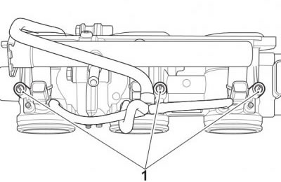
1. Air by-pass adjustment screws
11. When balanced, stop the engine and disconnect the diagnostic tool.
12. Disconnect the fuel pressure gauge adaptor and wiring extension.
13. Remove the exhaust extraction hoses from the silencer.
Perform the following operations: